Current induction structure bringing convenience to adjustment of transformation ratio

A technology of mutual inductance structure and current, applied in the direction of variable inductor, inductor, transformer/inductor coil/winding/connection, etc., can solve the problem of measuring instrument burnout, inaccurate reading accuracy, too small secondary current, etc. problems, to achieve the effect of reducing security risks and wide applicability

Inactive Publication Date: 2015-05-20
SICHUAN LANXUNBAOER ELECTRONICS TECH
View PDF10 Cites 4 Cited by
  • Summary
  • Abstract
  • Description
  • Claims
  • Application Information

AI Technical Summary

Problems solved by technology

Since the primary current is the current of the line to be tested, its value may change in different working periods. For the constant ratio current transformer, the following problems may occur: (1) The secondary current is too small, and the measuring instrument is not enough to drive the work, and the reading is 0 or the accuracy is inaccurate; (2) The secondary current is too large, and the measuring instrument is burned out after a long time of work, causing serious safety problems

Method used


Image

  • Current induction structure bringing convenience to adjustment of transformation ratio
  • Current induction structure bringing convenience to adjustment of transformation ratio

Examples


Embodiment 1

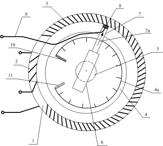
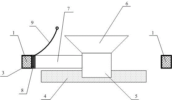
[0022] Embodiment one, figure 1 It shows the plan view of the current mutual inductance structure that is convenient for variable ratio adjustment provided by this embodiment, figure 2 It shows a vertical cross-sectional view of the current mutual inductance structure provided by this embodiment to facilitate variable ratio adjustment. The current mutual induction structure that is convenient for variable ratio adjustment is characterized in that it includes a circular closed iron core 1, a primary winding coil 2 and a secondary winding coil 3 spirally wound on the outer periphery of the iron core 1, a base 4, a rotating Shaft 5, handle 6, insulating rod 7, conductive contact 8 and outer lead wire 9; said rotating shaft 5 is arranged on the center position of the annular iron core 1 and above the base 4, and the lower end of the rotating shaft 5 rotates the connecting base Seat 4, the upper end of the rotating shaft 5 is connected to the handle 6, the middle part of the rota...


PUM


Abstract

The invention relates to the technical field of electrical equipment detection, and discloses a current induction structure bringing convenience to adjustment of a transformation ratio. The current induction structure bringing convenience to adjustment of the transformation ratio changes a contacting position of a conductive contact and an inner side wire of a secondary winding coil by acting a rotation shaft through a handle, further changes winding coil turns between an outer lead and one head end of the secondary winding coil, and finally achieves adjustment of the transformation ratio for a current transformer, thereby being suitable for circuits to be tested in different periods, reducing potential safety risks and being higher in applicability.

Description

technical field [0001] The invention relates to the technical field of electric equipment detection, in particular to a current mutual inductance structure that is convenient for variable ratio adjustment. Background technique [0002] Current Transformer (CT for short) is an electrical device that converts a large primary current into a small secondary current through a certain transformation ratio based on the principle of electromagnetic induction for protection or measurement purposes. A current transformer is generally composed of a closed iron core and a winding coil. The number of turns of the primary winding coil is small, and it is connected in series in the line to be tested. The current in the line to be tested is the primary current with a large value; the secondary winding The number of turns of the coil is more, because the size of the current is inversely proportional to the number of turns of the corresponding winding coil, so the secondary current is small, ...

Claims


Application Information

Patent Timeline
Patent Type & Authority Applications(China)
IPC IPC(8): H01F38/30H01F29/02H01F27/28G01R15/18
Inventor 李胜峰
Owner SICHUAN LANXUNBAOER ELECTRONICS TECH
Why Eureka
Try Eureka