power feed system

A technology of power feeding and power, which is applied in the field of power feeding systems, and can solve problems such as increased loss and increased loss

Inactive Publication Date: 2016-02-24
YAZAKI CORP
View PDF8 Cites 0 Cited by
  • Summary
  • Abstract
  • Description
  • Claims
  • Application Information

AI Technical Summary

Problems solved by technology

[0010] Therefore, when the operating frequency is fixed close to 13.5 megahertz (MHz), the inter-coil distance L 1 After 200mm, the passing characteristic S21 becomes close to 1, resulting in high efficiency, while if the distance between coils L 1 Change to 100mm, then the passing characteristic S21 drops to close to 0.64, causing the loss to increase
[0011] On the other hand, the inter-coil distance L 1 The longer the length, the looser the coupling between the power feeding side helical coil 7 and the power receiving side helical coil 9, causing mutual impedance matching decoupling, thus increasing the loss
[0012] It can be seen from the above that the distance L between the coils has been caused 1 Variations in the power feeding efficiency from the power feeding unit 3 to the power receiving unit 5 vary, thereby increasing the disadvantage of loss
Furthermore, it has resulted in Figure 9 The disadvantage shown, when a lateral offset x occurs, i.e. the axis is shifted between the power feeding side loop antenna 6 or the power feeding side helical coil 7 and the power receiving side loop antenna 10 or the power receiving side helical coil 9 , the distance L between the coils 1 Variations in also cause changes in power feeding efficiency from the power feeding unit 3 to the power receiving unit 5, thereby increasing losses

Method used


Image

  • power feed system
  • power feed system
  • power feed system

Examples


no. 1 example

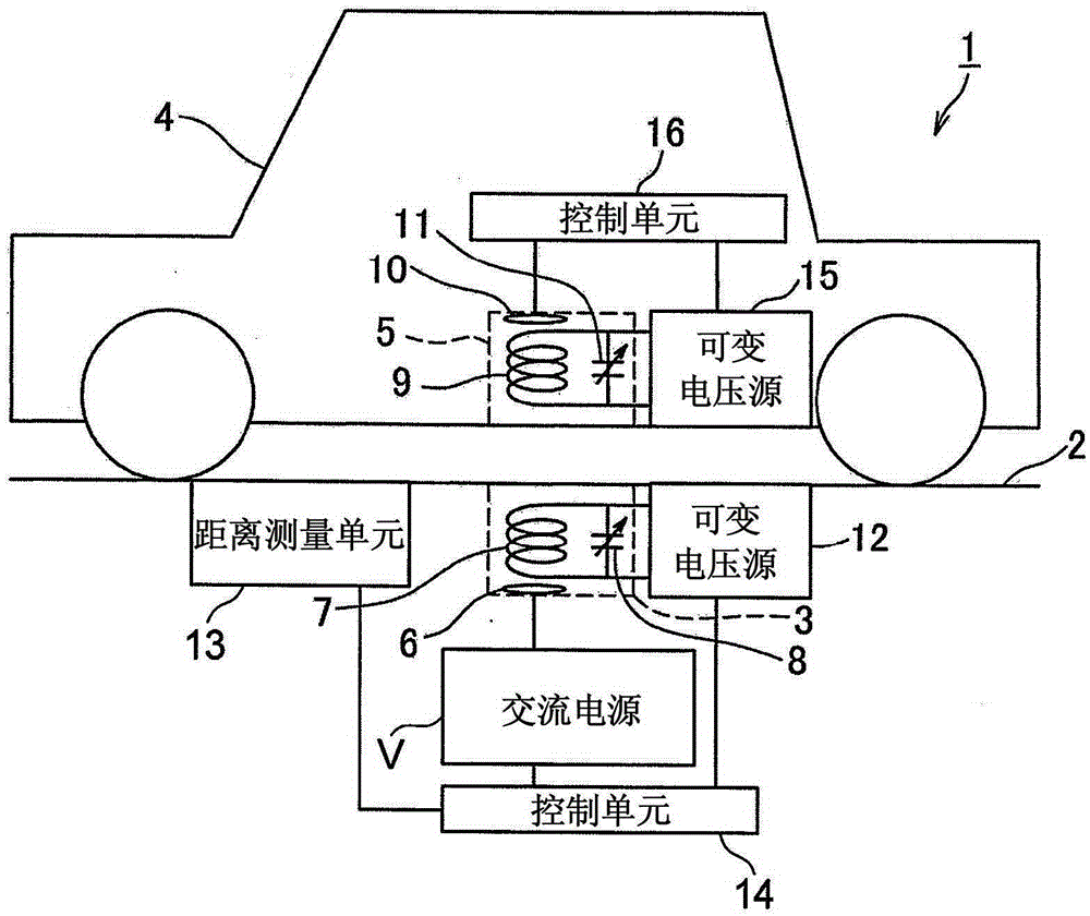
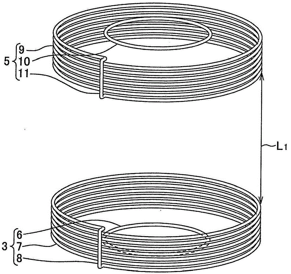
[0091] Hereinafter, the power feeding system of the present invention is described with reference to the drawings. figure 1 The power feeding system of the present invention is shown in the first embodiment. figure 2 to show figure 1 Perspective view of the construction of the power feed system shown. Such as figure 2 As shown, the power feeding system 1 has: a power feeding unit 3 provided on a road 2 as a feeding member; and a power receiving unit 5 installed in the body of an automobile 4 .

[0092] Such as figure 1 and figure 2 As shown, the above-mentioned power feeding unit 3 has: a power feeding side loop antenna 6 to be supplied with power; a power feeding side helical coil 7, as a power feeding side coil, electromagnetically coupled with the power feeding side loop coil 6; A diode 8, as a capacitor, is connected in parallel with the power feeding side helical coil 7. This power feeding side loop antenna 6 has a circular shape whose axis is arranged in the ...

no. 2 example

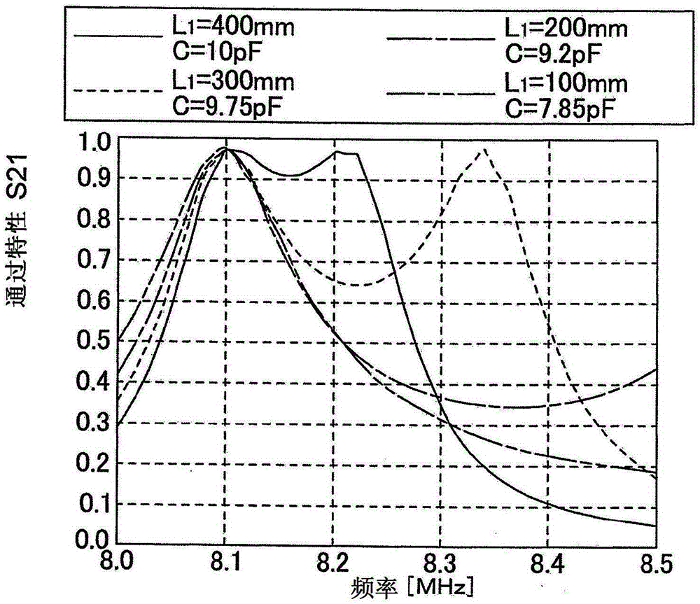
[0121] Next, a second embodiment will be described. Although in the first embodiment described above, based on the inter-coil distance L measured by the distance measuring unit 13 1 , to adjust the capacitance C of the varactor diodes 8, 11 on the power feeding side and the power receiving side, but in the second embodiment, on the other hand, as Figure 7 As shown, it is conceivable that instead of the distance measuring unit 11, a reflection measuring unit 18 is provided in the automobile 4 for measuring the reflection amount of the power receiving side helical coil 9, the power feeding side varactor 8 is removed, and the power receiving side is separately provided The varactor 11, and the capacitance C of the power receiving side varactor 11 is adjusted by the control unit 16, so that the reflection characteristic S21 is improved. It should be noted that the above-mentioned reflection measurement unit 18 is a unit that measures the power fed to the power receiving side hel...

no. 3 example

[0130] Next, a power feeding system of the present invention in a third embodiment will be described with reference to the drawings. Figure 10 The power feeding system of the present invention in the third embodiment is shown. Figure 11A and Figure 11B respectively show the depiction Figure 10 Schematic perspective and side views of the structure of the power feed system shown. In these figures, for figure 1 Corresponding parts of the power feeding system shown in the first embodiment described above are affixed with the same reference symbols, and a detailed description thereof is omitted. As shown in these figures, the third embodiment differs from the first embodiment in the absence of variable capacitors 8, 11, variable voltage sources 12, 15, distance measuring unit 13 and control units 14, 16 and power receiving The structure of the side loop antenna 10. It should be noted that although Figure 11A is shown with a circle for simple description, but the power r...


PUM


Abstract

The present invention discloses a power feeding system that can efficiently feed power from the power feeding side to the receiving unit. The distance measuring unit (13) measures the inter-coil distance (L1) between the power feeding side helical coil (7) and the power receiving side helical coil (9), and the control units (14, 16) ) to adjust the capacitance of the power feeding side varactor diode (8) and the power receiving side varactor diode (11) by measuring the inter-coil distance (L1).

Description

technical field [0001] The present invention relates to a power feeding system, and in particular, to a power feeding system for supplying electric power from a power feeding side coil to a power receiving side coil in a contactless manner. Background technique [0002] Power feed systems as mentioned above are well known such as Figure 29 (see Patent Documents 1 and 2) shown in the power feeding system. As shown in the figure, the power feeding system 1 has: a power feeding unit 3 as a power feeding unit member; and a power receiving unit 5 as a power receiving unit member. The power feeding unit 3 described above has: a power feeding side loop antenna 6 to which power is supplied; and a power feeding side helical coil 7 electromagnetically coupled with the power feeding side loop antenna 6 as a power feeding side coil. When power is supplied to the above-mentioned power feeding side loop antenna 6, the power is transmitted to the power feeding side helical coil 7 by elec...

Claims


Application Information

Patent Timeline
Patent Type & Authority Patents(China)
IPC IPC(8): H02J50/12
CPCB60L2210/30B60L2210/40Y02T90/12Y02T90/14Y02T10/7072B60L53/36B60L53/126B60L53/122H02J50/12H02J50/90Y02T10/70Y02T10/72H02J50/80H01F38/14
Inventor 田中信吾堀内学
Owner YAZAKI CORP
Why Eureka
Try Eureka