Permanent-magnet synchronous motor

A permanent magnet synchronous motor and magnetic slot technology, which can be applied to motors, synchronous motors with stationary armatures and rotating magnets, magnetic circuits, etc. The effect of speed regulation range and high power density

Active Publication Date: 2015-05-20
ZHEJIANG TOP MOTORING TECH
View PDF7 Cites 31 Cited by
  • Summary
  • Abstract
  • Description
  • Claims
  • Application Information

AI Technical Summary

Problems solved by technology

However, it is clear that the motor has not been considered in terms of size and cost, and there is still room for improvement in power density.

Method used


Image

  • Permanent-magnet synchronous motor
  • Permanent-magnet synchronous motor
  • Permanent-magnet synchronous motor

Examples


Embodiment 1

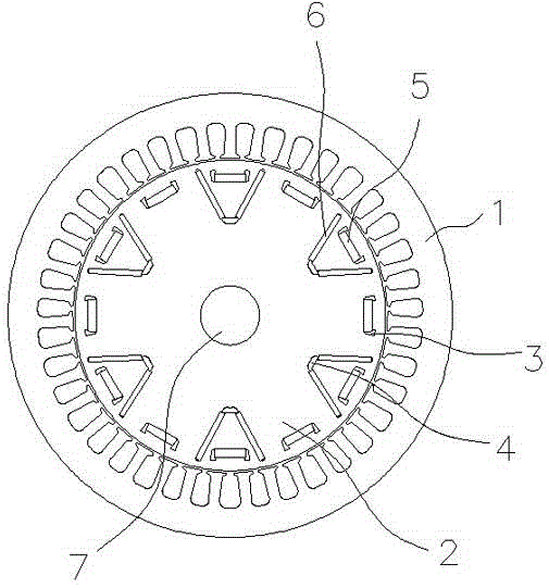
[0026] A permanent magnet synchronous motor, such as figure 1 As shown, it includes the rotor 2 and the stator 1 arranged in the rotor 2. The rotor 2 includes a rotor core as a support. A number of magnetic grooves are engraved on the rotor core. The magnetic steel groups are embedded in the magnetic grooves, and the magnetic grooves are evenly arranged. On the circumference of the cross-section of the rotor core, the magnetic slots include a first magnetic slot 4 and a second magnetic slot 3, the second magnetic slot 3 is close to the circumferential edge of the rotor core cross-section, and the number of the first magnetic slots 4 is the second Half of the number of magnetic slots 3 , the first magnetic slots 4 and the second magnetic slots 3 correspond alternately and are arranged between the corresponding second magnetic slots 3 and the rotating shaft 7 of the rotor core.

[0027] The second magnetic slot 3 is provided with an outer magnetic steel group 5. The outer magnet...

Embodiment 2

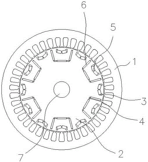
[0032] The difference from Embodiment 1 is that, as figure 2As shown, the outer magnetic steel group 5 includes a "V"-shaped outer magnet whose cross-section is open outward, and the included angle of the outer magnet is an obtuse angle.

[0033] The cross-section of the first magnetic slot 4 is a "U" shape with the opening pointing to the circumference of the cross-section of the rotor core. The inner magnetic steel group 6 includes 3 inner magnets, which are respectively arranged on the two sides and one bottom of the "U" shape. side.

Embodiment 3

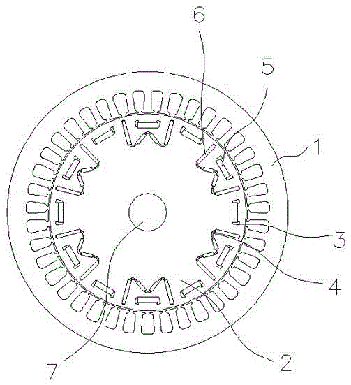
[0035] The difference from Embodiment 1 is that, as image 3 As shown, the cross-section of the first magnetic slot 4 is a "W" shape with the opening pointing to the circumference of the cross-section of the rotor core. The inner magnetic steel group 6 includes four rectangular inner magnets, which are respectively arranged on the "W" "The 4 sides of font.


PUM


Abstract

The invention relates to a permanent-magnet synchronous motor, which comprises a rotor and a stator arranged outside the rotor, the rotor comprises a rotor core, the rotor core is provided with magnet slots, and magnetic steel groups are inserted in the magnet slots. The permanent-magnet synchronous motor is characterized in that the magnet slots are evenly arranged along the circumferential direction of the rotor core, the magnet slots are first magnet slots and second magnet slots, the second magnet slots are closer to the periphery of the rotor core than the first magnet slots, the number of the first magnet slots are half of the number of the second magnet slots, the first magnet slots and the second magnet slots staggerly correspond to each other, and moreover, the first magnet slots are arranged between the second magnet slots corresponding to the first magnet slots and a rotary shaft of the rotor core; the outer magnetic steel groups are arranged in the second magnet slots, and the inner magnetic steel groups are arranged in the first magnet slots. The motor disclosed by the invention is put forward under the current special requirement of power systems of electric vehicles on driving motors, and the motor has the advantages of high power density, wide speed regulation range and low popularization cost.

Description

technical field [0001] The invention relates to a motor, in particular to a permanent magnet synchronous motor. Background technique [0002] In order to save energy and reduce carbon emissions, there are more and more electric and gasoline-electric hybrid models. Most of these models use permanent magnet synchronous motor solutions. The output torque of permanent magnet synchronous motors is proportional to the working current and back EMF coefficient of the motor. The permanent magnet synchronous motor needs to use a special controller to run continuously. When the permanent magnet synchronous motor has a wide speed range operation requirement, it is often encountered in engineering that the controller’s drive current capability is insufficient or the device’s withstand voltage capability is insufficient, especially the highest motor. The no-load back EMF voltage at speed is not enough. In order to take into account the wide speed range and power performance of the motor,...

Claims


Application Information

Patent Timeline
Patent Type & Authority Applications(China)
IPC IPC(8): H02K21/14H02K1/27
CPCH02K1/276H02K21/14Y02T10/64
Inventor 袁沛海
Owner ZHEJIANG TOP MOTORING TECH
Why Eureka
Try Eureka