A roller bearing sleeve installation machine

A bearing sleeve and installation machine technology, which is applied in the field of roller manufacturing, can solve the problems of low efficiency of manual alignment operation, reduced service life, skewed roller axis, etc., and achieve high equipment space utilization, low manufacturing cost, and installation accuracy high effect

Active Publication Date: 2017-02-01
河北骥驰耐磨材料有限公司
View PDF5 Cites 0 Cited by
  • Summary
  • Abstract
  • Description
  • Claims
  • Application Information

AI Technical Summary

Problems solved by technology

It is time-consuming and labor-intensive for workers to install the bearing sleeve manually. When stamping the bearing sleeve, it must be ensured that the axis of the bearing sleeve cannot be skewed with the axis of the outer diameter of the porcelain. Exacerbated roller wear and reduced service life

Method used


Image

  • A roller bearing sleeve installation machine
  • A roller bearing sleeve installation machine
  • A roller bearing sleeve installation machine

Examples


Embodiment Construction

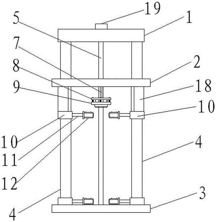
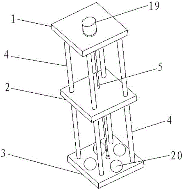
[0021] A roller bearing sleeve installation machine, including a press, a machine base 3, a lifting platform 2 and a machine top plate 1, the machine base 3 and the machine top plate 1 are fixed by four vertical longitudinal beams 4 evenly distributed at the four corners of the machine base 3 connected to form a rack (see figure 2 ), the lifting platform 2 is located between the machine base 3 and the top plate 1, the four corners of the lifting platform 2 are provided with cavities, the four longitudinal beams 4 pass through the lifting platform 2, the upper and lower sides of the machine base 3, the lifting platform 2, and the machine top plate 1 are all It is square and parallel to each other. A screw pair is arranged in the middle of the lifting platform 2. The nut of the screw pair is fixedly connected with the lifting platform 2. The screw shaft 5 of the screw pair is perpendicular to the lifting platform 2, and the screw shaft 5 is fixed on the machine. On the bearing ...


PUM


Abstract

The invention relates to the technical field of carrier roller manufacturing and in particular discloses a carrier roller and bearing housing mounting machine. The mounting machine comprises a press machine, an engine base, a lifting table and a machine top plate, wherein the engine base and the machine top plate are fixedly connected by virtue of a vertical longitudinal beam; the lifting table can be vertically moved and positioned between the engine base and the machine top plate by virtue of a power lifting device; the lower end of the lifting table is fixedly connected with the press machine; a punch of the press machine is perpendicular to the engine base; the lower end surface of the punch is a plane; an annular positioning groove is formed in a position, which vertically corresponds to the punch, of the engine base; the center of the annular positioning groove is coincided with the axis of the punch; and the outer diameter of the annular positioning groove is the same as the outer diameter of a porcelain body. The bearing housing mounting machine also comprises a porcelain body fixing device and a punch buffer sleeve, so that the alignment accuracy of the bearing housing is improved, the phenomenon that the bearing housing is taken away by the punch is eliminated, and the yield is improved. According to the device, the operation of manually mounting the bearing housing can be replaced, the labor intensity of workers is reduced, and the machine is stable to mount and high in efficiency.

Description

technical field [0001] The invention relates to the technical field of roller manufacturing. Background technique [0002] The idler roller is the main part of the conveyor. The ceramic idler roller has the advantages of corrosion resistance, high strength and long service life, and is widely used in steel, coking, chlor-alkali, chemical fertilizer and other industries. The ceramic roller is mainly composed of a porcelain body, a bearing sleeve, a plastic sealing ring and a bearing sleeve. The porcelain body is hollow and penetrates the shaft horizontally. The two ends of the porcelain body are fixed with the bearing sleeve. The bearing sleeve is filled with a bearing, and the outside of the bearing is sealed with a plastic sealing ring , the bearing is sealed in the bearing housing. [0003] The bearing sleeve is also called the bearing seat, see Figure 5 , generally consists of a sleeve and an extension. The bottom of the sleeve is provided with a bottom plate, which shr...

Claims


Application Information

Patent Timeline
Patent Type & Authority Patents(China)
IPC IPC(8): B23P19/02
CPCB23P19/02
Inventor 成树峰
Owner 河北骥驰耐磨材料有限公司
Why Eureka
Try Eureka