
Method for producing an endless transport belt

A technology of endless transmission and transmission belt, which is applied in the direction of belt fasteners, conveyors, mechanical equipment, etc., can solve the problems of small ink concentration, reduce the quality of printing samples, etc., and achieve the effect of reducing grinding work

Inactive Publication Date: 2015-05-27
MANROLAND WEB SYST
View PDF10 Cites 2 Cited by
  • Summary
  • Abstract
  • Description
  • Claims
  • Application Information

AI Technical Summary

Problems solved by technology

Samples printed in the seam area therefore have less ink density, resulting in reduced quality of printed samples

Method used


Image

  • Method for producing an endless transport belt
  • Method for producing an endless transport belt
  • Method for producing an endless transport belt

Examples


Embodiment Construction

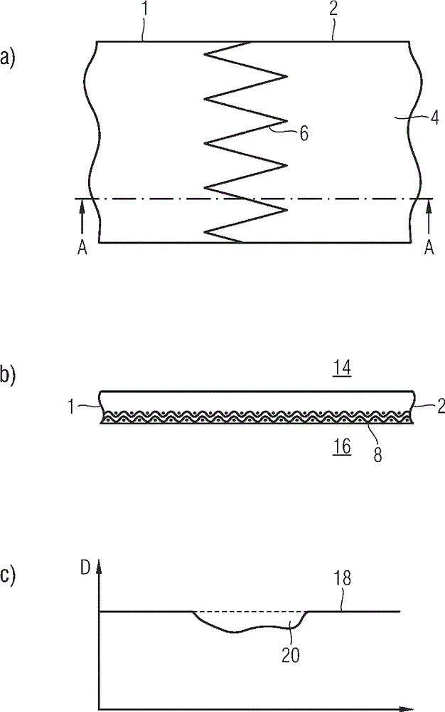
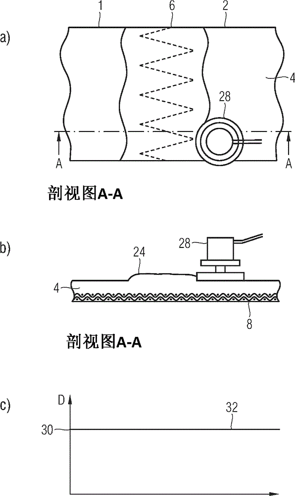
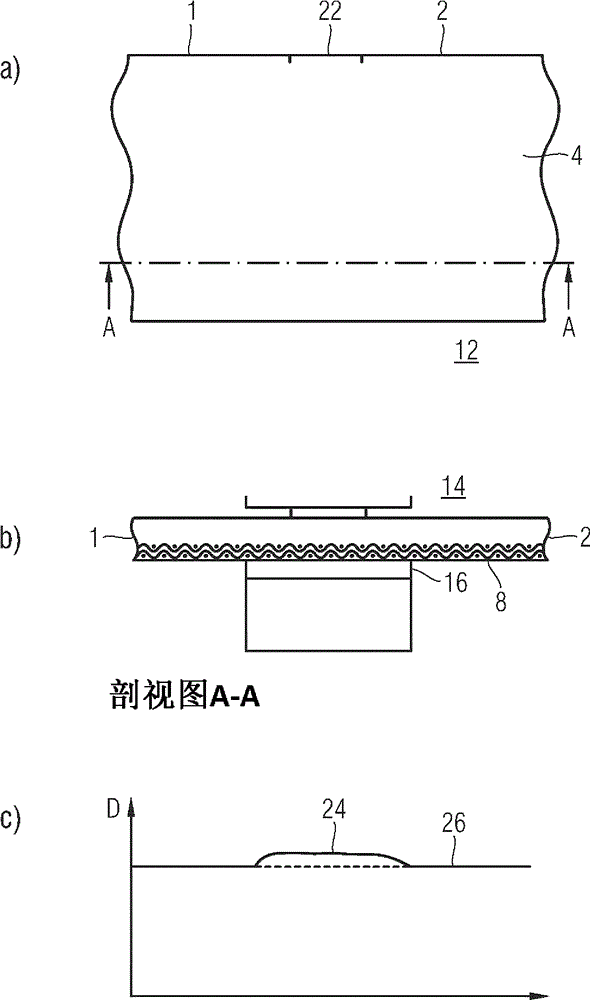
[0023] in accordance with figure 1 In the examples, the welding process without additional material addition is described. The ends 1 , 2 of the conveyor belt 4 are designed in a wedge-tooth shape and engage with each other at the seam 6 . figure 1 In b, a cross section through the conveyor belt 4 in the region of the weld seam, ie the seam 6 , is shown during the welding process. The structure of the conveyor belt 4 can be seen more clearly in cross section. It consists of a textile fabric layer 8 and a cover layer 10 which is coated with an adhesive. The welding process is carried out by means of a heat press 12 comprising an upper heating plate 14 and a lower heating plate 16 with which temperatures of approximately 160° C. can be achieved. The two ends 1 , 2 of the conveyor belt 4 are connected to one another in a materially bonded manner by means of the heating plate. If according to figure 1 The thickness sectional view 18 of c shows that the groove 20 is formed in ...


PUM


Abstract

A method for producing an endless transport belt for guiding substrates during the printing operation of a printing press is disclosed. The ends of a transport belt are welded together. The transport belt is ground, after one or multiple welding operations without or with the addition of material, to a nominal thickness that is smaller than or equal to the minimal thickness of the transport belt.

Description

technical field [0001] The invention relates to a method for the production of an endless conveyor belt for transporting substrates during the printing process of a printing press, wherein the ends of the conveyor belt are welded. Background technique [0002] Such endless conveyor belts have been known for a long time in order to guide flat material webs, in particular material webs consisting of critical material, for example with a tendency to bend, reliably through, for example, printing presses machine. Such conveyor belts are disclosed, for example, in the texts WO 82 / 00975, DE10023689, DE8915358. Such conveyor belts mostly consist of a multilayer construction in which the textile fabric layer absorbs the tension and in which the cover layer is designed in such a way that the cover layer can be coated with an adhesive that is produced in the Connection between tape and substrate. Current endless conveyor belts consist mainly of polyurethane, which are especially wel...

Claims


Application Information

Patent Timeline
Patent Type & Authority Applications(China)
IPC IPC(8): B41F21/00
CPCF16G3/10B29L2031/7092B65G15/34B29C65/749
Inventor S. 阿尔布雷希特N. 罗滕贝格尔X. 巴赫迈尔S. 菲舍尔M. 伊劳斯H. 施图尔米勒
Owner MANROLAND WEB SYST
Learn More