

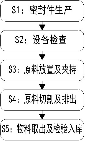
Sealing part machining method
A processing method and technology for sealing parts, applied in the field of sealing parts processing, can solve the problems of reducing the efficiency of cutting tools, safety of tool scratches, affecting the use effect, etc., and achieve the effect of avoiding production efficiency, reducing hidden dangers of installation and consistent spacing.
- Summary
- Abstract
- Description
- Claims
- Application Information
AI Technical Summary
Problems solved by technology
Method used
Image

Examples
Embodiment Construction
[0044] The embodiments of the present invention will be described in detail below with reference to the accompanying drawings, but the present invention can be implemented in many different ways defined and covered by the claims.
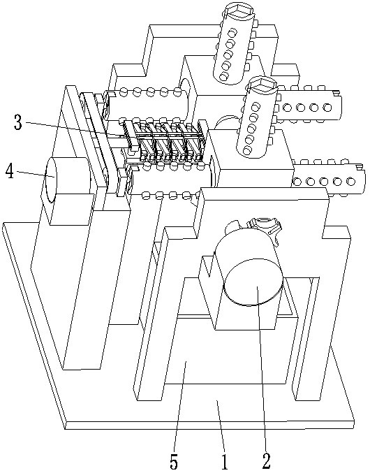
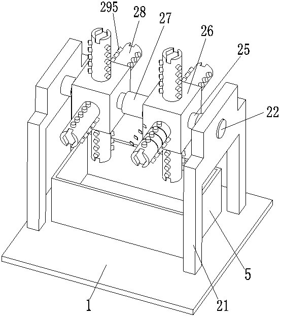
[0045] Such as Figure 1 to Figure 11 As shown, a seal processing method, the seal processing method adopts the following seal processing device, the seal processing device includes a base 1, a charging mechanism 2, a cutting mechanism 3, a rotating mechanism 4 and a receiving box 5, the base The upper end surface of 1 is provided with a charging mechanism 2, a cutting mechanism 3 and a rotating mechanism 4 in sequence from right to left, and the rotating mechanism 4 is connected with the cutting mechanism 3 and the charging mechanism 2 respectively, and the upper end surface of the base 1 is located on the charging mechanism 2. A receiving box 5 with a box-type mechanism is installed below;
[0046]During specific work, the present invention can a...
PUM
 Abstract
Description
Claims
Application Information