
pneumatic pile driver

A pile driver and gas circuit technology, applied in sheet pile walls, buildings, infrastructure engineering, etc., can solve the problems of easy deflection, low efficiency, and potential safety hazards of driven piles, and achieve rapid and smooth exhaust and air intake The effect of rapidity and shortened cycle process

Inactive Publication Date: 2016-09-07
HEBEI HONGDE PLASTIC HARDWARE PROD
View PDF6 Cites 0 Cited by
  • Summary
  • Abstract
  • Description
  • Claims
  • Application Information

AI Technical Summary

Problems solved by technology

[0002] For small-scale piling or pile planting in building construction, the piles to be implanted are generally manually tapped with a sledgehammer to drive the piles into the ground. This construction method is time-consuming, laborious, inefficient, and The piles are easy to deflect, which is easy to cause safety hazards

Method used


Image

  • pneumatic pile driver
  • pneumatic pile driver
  • pneumatic pile driver

Examples


Embodiment Construction

[0020] The present invention will be further described in detail below in conjunction with the accompanying drawings and specific embodiments.

[0021] gas The dynamic pile driver is a mechanized hand tool that uses compressed air as the power source to generate mechanical impact and strike the workpiece object. It is suitable for hammering steel drill piles and other similar piles to the ground on the construction site. It is a building frame and It is an ideal piling tool for electric ground piles and other industries. It can replace traditional manual sledgehammer strikes. It has large striking force, fast striking speed, high efficiency, convenient operation and low labor intensity.

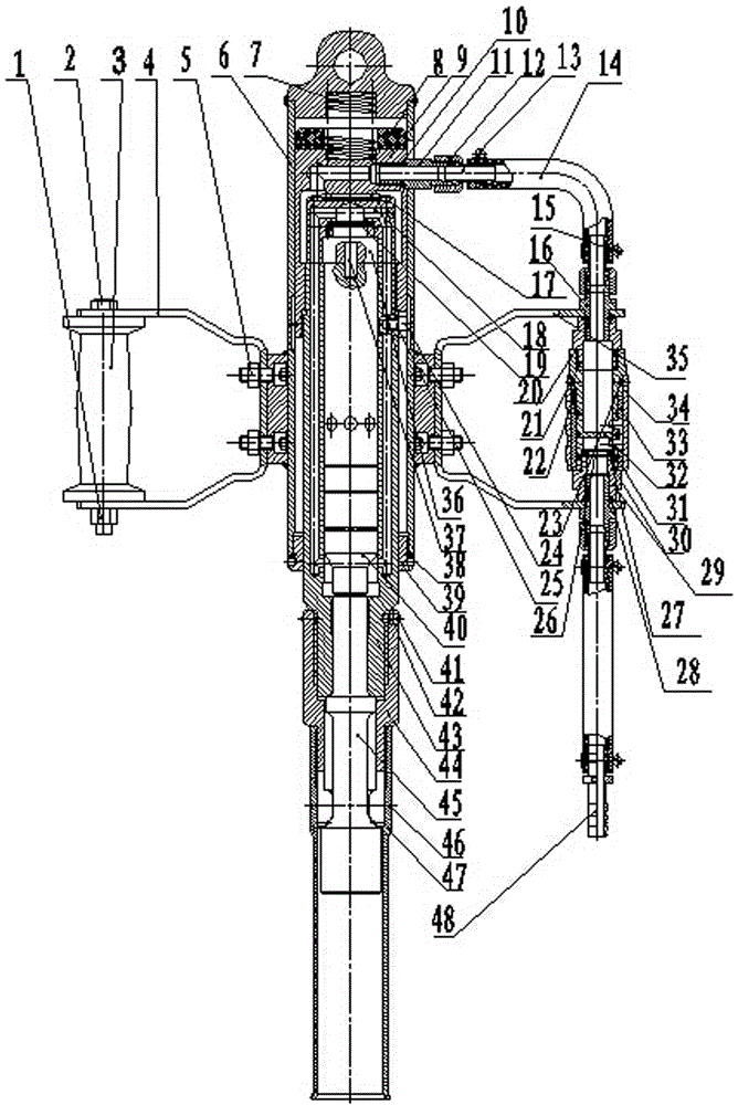
[0022] Concrete structure of the present invention sees figure 1 As shown, it includes a casing 6, a cylinder body 43, a valve cabinet 18, a valve plate 19, a valve cover 36, a coupling sleeve 9, an impact rod 45, and a hammer body 40. The coupling sleeve 9 is placed on the upper end of the...


PUM


Abstract

The invention discloses a pneumatic pile driver and relates to the technical field of pile drivers. The invention includes a shell, an impact rod, a hammer body, a casing, a cylinder, a valve cabinet, a valve plate, a valve cover, and a coupling sleeve. The outer wall of the shell is equipped with a left bracket and a right bracket with a handle, and the coupling sleeve is placed on the The upper end of the shell shell, the valve plate and the valve cover of the valve cabinet are placed in the coupling sleeve from top to bottom. The upper end of the cylinder body is provided with external threads, and the lower end of the coupling sleeve is provided with internal threads. The upper end surface is in contact with the lower end surface of the valve cover, the valve cabinet, the valve cover and the cylinder body are positioned and connected by the second cylindrical pin, the air passage hole of the valve cabinet, the air hole of the valve cover and the lower air inlet hole of the cylinder body are vertically connected, and The communication hole at the lower end of the cylinder body communicates with the inner cavity of the cylinder body. The middle part of the cylinder body is provided with an exhaust hole that is not connected with the lower air intake hole. The exhaust hole communicates with the inner cavity of the cylinder body. The gas path rotary switch on the top enters the coupling sleeve and communicates with the gas path of the valve cabinet valve cover and the cylinder body. The invention has the advantages of unobstructed air flow, strong striking force, fast striking speed and high piling efficiency.

Description

technical field [0001] The invention relates to a pile driver, in particular to a pneumatic pile driver. Background technique [0002] For small-scale piling or pile planting in building construction, the piles to be implanted are generally manually tapped with a sledgehammer to drive the piles into the ground. This construction method is time-consuming, laborious, inefficient, and The piles are easy to deflect, which is easy to cause safety hazards. Contents of the invention [0003] The technical problem to be solved by the present invention is to provide a pneumatic pile driver, which is easy to operate, strong in striking force, fast in striking speed and high in piling efficiency. [0004] In order to solve the above-mentioned technical problems, the technical solution adopted by the present invention is: a pneumatic pile driver, including a casing, an impact rod, a hammer body, a casing, a cylinder body, a valve cabinet, a valve plate, a valve cover, a coupling slee...

Claims


Application Information

Patent Timeline
Patent Type & Authority Patents(China)
IPC IPC(8): E02D7/10
CPCE02D7/10
Inventor 张效铭
Owner HEBEI HONGDE PLASTIC HARDWARE PROD
Learn More