Supercharge Your Innovation With Domain-Expert AI Agents!

Microcomputer intelligent grouting system and operation method thereof

An operation method and microcomputer technology, applied in the direction of mixing operation control, chemical instruments and methods, mixing plants, etc., can solve the problems of rapid loss of fluidity, easy segregation and stratification, and easy deviation of the proportion, so as to achieve full and dense grouting, Uniform slurry distribution and precise control

Active Publication Date: 2015-05-27
LIUZHOU JUNENG ELECTRIC
View PDF4 Cites 6 Cited by
  • Summary
  • Abstract
  • Description
  • Claims
  • Application Information

AI Technical Summary

Problems solved by technology

[0005] 1. Poor compatibility of various admixtures caused by the easy deviation of the proportion, poor adaptability between cement and admixtures, resulting in the following serious problems in channel grouting:
[0006] 2. Poor slurry quality stability, poor fluidity, rapid loss of fluidity, poor volume stability;
[0007] 3. The prepared slurry has a high bleeding rate, is easy to segregate and stratify, and the pores are difficult to become full;
[0008] 4. After filling, the slurry is not dense and has a lot of porosity

Method used


Image

  • Microcomputer intelligent grouting system and operation method thereof
  • Microcomputer intelligent grouting system and operation method thereof
  • Microcomputer intelligent grouting system and operation method thereof

Examples


Embodiment Construction

[0047] Below in conjunction with accompanying drawing, preferred embodiment of the present invention is described in further detail:

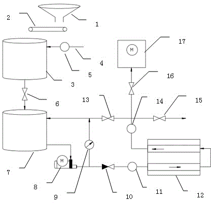
[0048] see figure 1 and 2, a microcomputer intelligent grouting system, comprising a silo 1, a belt weighing scale 2 positioned at the bottom of the silo 1, a high-speed mixing tank 3 located below the belt weighing scale 2, and a pulp storage tank 7 below the high-speed mixing tank 3 1. Connect the grouting pump 8 of the slurry storage barrel 7 through a rubber tube and the vacuum pump 17 connected to the grouting pump 8 through a tunnel 12, and connect the rubber tube between the high-speed mixing barrel 3 and the slurry storage barrel 7 There is a grouting valve 6 on it; a grouting stop valve 10 and a grouting pressure gauge 11 are arranged on the rubber tube connecting the grouting pump 8 and the tunnel 12; a rubber tube connecting the grouting pump 8 and the vacuum pump 17 There is a slurry return pressure gauge 14 and a vacuum valve 16;...


PUM


Abstract

The invention discloses a microcomputer intelligent grouting system, which comprises a material cabin, a belt metering balance, a high-speed stirring barrel, a slurry storage barrel, a grouting pump, a vacuum pump, a slurry discharging valve, a grouting stop valve, a grouting pressure meter, a slurry return pressure meter and a vacuum valve, wherein the belt metering balance is positioned at the bottom of the material cabin, the high-speed stirring barrel is positioned under the belt metering balance, the slurry storage barrel is arranged under the high-speed stirring barrel, the grouting pump is connected with the slurry storage barrel through a rubber pipe, the vacuum pump is connected with the grouting pump through a hole passage, the slurry discharging valve is connected between the high-speed stirring barrel and the slurry storage barrel, the grouting stop valve and the grouting pressure meter are connected onto a rubber pipe arranged between the grouting pump and the hole passage, the slurry return pressure meter and the vacuum valve are connected onto a rubber pipe arranged between the hole passage and the vacuum pump, a rubber pipe connected between the slurry return pressure meter and the vacuum pump is connected with the slurry storage barrel, and a slurry return valve is arranged on a rubber pipe arranged between the slurry return pressure meter and the slurry storage barrel. The fluidity and the quality stability of slurry are improved, the hole passage is full after the grouting, the slurry is compact after the filling, and the control is precise.

Description

technical field [0001] The invention relates to the field of prestressed concrete beam construction, in particular to a microcomputer intelligent grouting system and an operating method thereof. Background technique [0002] At present, in the construction of prestressed engineering such as construction projects and highway bridge projects in China, the grouting process of the prestressed tunnel is generally: before grouting, use a vacuum pump to vacuum the tunnel at one end of the tunnel to generate a vacuum of about -0.1MPa Then use the grout pump to pour the optimized special cement slurry from the other end of the tunnel until it covers the entire tunnel, and add a positive pressure of not less than 0.7MPa to improve the fullness of the prestressed tunnel grouting and density. [0003] Since the above processes are all controlled by humans, including process control and control of the process end point, this involves more process control points, such as the cleaning and...

Claims


Application Information

Patent Timeline
IPC IPC(8): E04G21/02E01D21/00B28C9/02E01D101/28
Inventor 区佐乙
Owner LIUZHOU JUNENG ELECTRIC
Features
  • R&D
  • Intellectual Property
  • Life Sciences
  • Materials
  • Tech Scout
  • Unparalleled Data Quality
  • Higher Quality Content
  • 60% Fewer Hallucinations
Learn More