Oil well pump plunger assembler and assembling method thereof

An oil pump and assembler technology, which is applied to the components of the pumping device for elastic fluid, pump components, variable displacement pump components, etc., can solve the problems of uneven installation torque, time-consuming and wasteful installation of the plunger, etc. , to achieve the effect of balanced tightness, uniform force on the thread, and improved service life

Active Publication Date: 2015-05-27
陕西延长石油机械装备制造有限公司
View PDF4 Cites 1 Cited by
  • Summary
  • Abstract
  • Description
  • Claims
  • Application Information

AI Technical Summary

Problems solved by technology

[0004] The object of the present invention is to provide a plunger assembler for an oil well pump, which solves the problems of time-consuming, labor-wasting and unequal installation torques when installing the plunger with the existing manual tools

Method used


Image

  • Oil well pump plunger assembler and assembling method thereof
  • Oil well pump plunger assembler and assembling method thereof
  • Oil well pump plunger assembler and assembling method thereof

Examples


Embodiment Construction

[0025] The present invention will be described in detail below in conjunction with the accompanying drawings and specific embodiments.

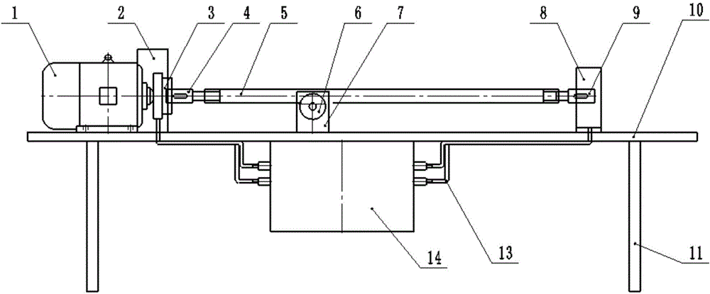
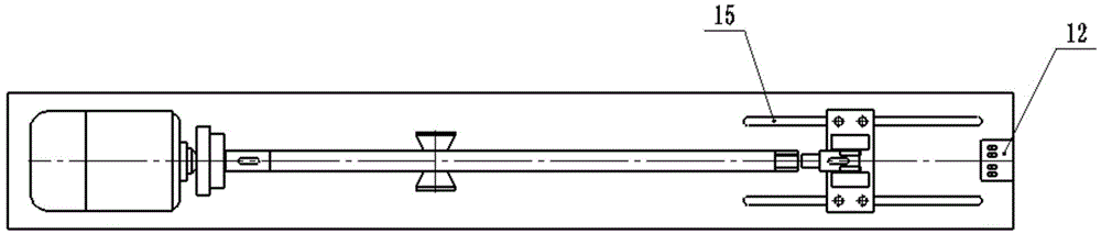
[0026] A plunger assembler of the present invention, such as figure 1 As shown, it includes a platform 10 and a low-speed motor 1. Below the platform 10 is a platform support leg 11. A motor 1 and a hydraulic clamp 8 are arranged on the platform 10. The low-speed motor 1 is connected to the hydraulic clamping head 3, and the hydraulic clamping head 3 A shield 2 for protection is arranged on the outside, and a centering wheel mounting plate 7 is provided at the middle position of the connection line between the hydraulic clamping head 3 and a hydraulic clamp 8, and the centering wheel 6 is installed on the centering wheel mounting plate 7. When installing, the middle part of the plunger 5 is supported by the centering wheel 6 . The hydraulic clamping head 3 clamps the upstream traveling valve 4, and the hydraulic clamp 8 clamps the downstream...


PUM


Abstract

The invention discloses an oil well pump plunger assembler which comprises a platform and a low-speed electric motor arranged on one side of the platform. Platform supporting legs are arranged under the platform, a hydraulic clamping head and a hydraulic clamp are arranged on the platform, the low-speed electric motor is connected with the hydraulic clamping head, a protection cover is arranged outside the hydraulic clamping head, and a straightening wheel installing plate and a straightening wheel are arranged in the middle of a connection line between the hydraulic clamping head and the hydraulic clamp. Thus, the problems of time waste, labor waste and unequal installation torque caused by installing plungers through manual tools in the prior art are solved. The invention further discloses an oil well pump plunger assembling method. An upper travelling valve and a lower travelling valve are firstly screwed to a plunger and are arranged on the hydraulic clamping head and the hydraulic clamp, the hydraulic clamping head and the hydraulic clamp tightly clamp the upper travelling valve and the lower travelling valve, the low-speed electric motor drives the hydraulic clamping head to rotate to fasten threads among the upper travelling valve, the plunger and the lower travelling valve, the low-speed electric motor is shut down, and the hydraulic clamping head and the hydraulic clamp are released.

Description

technical field [0001] The invention belongs to the technical field of oil extraction systems, and in particular relates to an oil well pump plunger assembler. The invention also relates to a method for assembling the oil well pump plunger by using the oil well pump plunger assembler. Background technique [0002] During the installation process of the oil pumping plunger, the upper and lower flow valve thread buckles must be screwed on one end with a special wrench, then turned over to the other end and then tightened with a wrench. This is a waste of time and it is difficult to control the torque. If it is not tight or too tight, it will cause harm to the plunger when it is working. [0003] In the prior art, there is a manual tool for assembling the plunger of the oil well pump, which has the problems of time-consuming, waste of manpower and unequal installation torque, so that the service life of the plunger of the oil well pump cannot be guaranteed. Contents of the i...

Claims


Application Information

Patent Timeline
Patent Type & Authority Applications(China)
IPC IPC(8): F04B53/22
Inventor 张锋冯小彦
Owner 陕西延长石油机械装备制造有限公司
Why Eureka
Try Eureka