Centrifugal fan

A centrifugal fan and impeller technology, which is used in mechanical equipment, non-variable-capacity pumps, machines/engines, etc., can solve the problems of increasing the noise of a single unit, and it is difficult to suppress the noise of a single unit. The effect of noise suppression

Active Publication Date: 2015-05-27
RINNAI CORP
View PDF7 Cites 3 Cited by
  • Summary
  • Abstract
  • Description
  • Claims
  • Application Information

AI Technical Summary

Problems solved by technology

[0008] However, if the diameter of the opening of the centrifugal fan is reduced, there is a tendency to increase the noise of the centrifugal fan alone, and there is a problem that although the resonance sound can be suppressed, it is difficult to suppress the noise of the single body.

Method used


Image

  • Centrifugal fan
  • Centrifugal fan
  • Centrifugal fan

Examples


Embodiment Construction

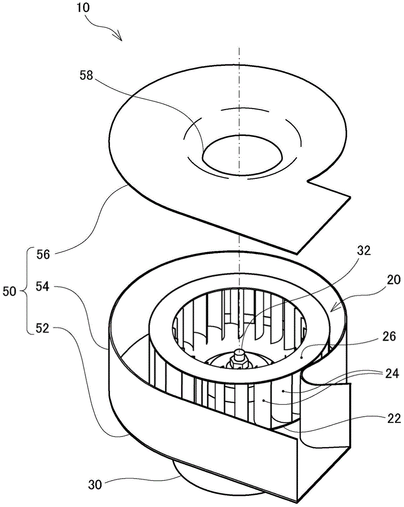
[0026] figure 1 It is a perspective view showing the disassembled state of the centrifugal fan 10 of this embodiment. The centrifugal fan 10 is connected to, for example, a combustion device (not shown) having a built-in burner, and is used to send combustion air to the burner. As shown, the centrifugal fan 10 includes an impeller 20 that generates wind by rotation, a driving motor 30 for rotating the impeller 20 , a fan housing 50 for accommodating the impeller 20 , and the like.

[0027] The impeller 20 of the present embodiment is a so-called multi-blade blower in which a plurality of blades 24 formed elongately in the axial direction of the rotating shaft 32 of the driving motor 30 are radially arranged with respect to the rotating shaft 32 at predetermined intervals. cylindrical shape. One end (lower end in the drawing) of the blade 24 is attached to the outer edge portion of the substantially circular rotating disc 22 , and the other end (upper end in the drawing) of ...


PUM


Abstract

The invention provides a centrifugal fan which can meanwhile restrain monomer noise of a centrifugal fan and resonance sound of equipment in the centrifugal fan. A cylindrical vane wheel formed by a plurality of blades vertically arranged on the external periphery of a rotary circular plate is accommodated in a volute; a cover plate provided with a bellmouth-shaped opening part and used for guiding air to inner sides of the vane wheel is employed to cover one end side of a rotary shaft on an axial direction. In addition, the opening part is eccentrically configured to be close to a tongue part (a connection part between a volute minor diameter side and an air supply path) and close to an opening center relative to the rotary shaft. Accordingly, compared with a case where the opening part is not eccentric, the centrifugal fan can narrow a disordered space caused by countercurrent on the periphery of the tongue part when air flows from the opening part to blades. As a result, the centrifugal fan can reduce an opening area of the opening part so as to restrain resonance sound, and monomer noise caused by turbulence caused by countercurrent.

Description

technical field [0001] The present invention relates to a centrifugal blower for blowing air into a combustion device and the like. Background technique [0002] A centrifugal fan is known as a blower used in a combustion apparatus or the like (for example, Patent Document 1). A centrifugal fan includes: a cylindrical impeller in which a plurality of blades are radially arranged with respect to a rotating shaft; and a volute for accommodating the impeller. The volute is formed in a cylindrical shape in which the radius of the impeller with respect to the rotating shaft increases along the rotating direction of the impeller, and a bell for guiding air to the inside of the impeller is formed on a cover plate covering one end side in the axial direction of the rotating shaft. Mouth-shaped opening. In addition, an air blowing passage is provided extending in a tangential direction from the peripheral surface of the volute on the larger radius side. When the impeller is rotate...

Claims


Application Information

Patent Timeline
Patent Type & Authority Applications(China)
IPC IPC(8): F04D29/44F04D29/66
CPCF04D29/441F04D29/663F04D29/422F04D29/4226F04D29/4233F04D29/44F04D29/665F04D29/667F04D29/668
Inventor 赤木万之宫岛征树泷启东志中谷立好
Owner RINNAI CORP
Why Eureka
Try Eureka