A tank fin welding structure and welding method

A technology of welding structure and welding method, which is applied in the direction of welding equipment, auxiliary welding equipment, welding/cutting auxiliary equipment, etc., can solve the problems that the accumulated water in the tank fin cannot automatically flow into the tank, damage the inclined surface of the stainless steel tank fin, etc., and avoid harmful deformation effect

Active Publication Date: 2017-07-07
宁波聚利金属制品有限公司
View PDF6 Cites 0 Cited by
  • Summary
  • Abstract
  • Description
  • Claims
  • Application Information

AI Technical Summary

Problems solved by technology

[0007] The invention designs a tank fin welding structure and welding method, which solves the technical problem that in the existing tank fin welding process, a large amount of heat generated by welding will cause the tank fin to form an uneven structure, and the uneven structure will damage the stainless steel tank The slope of the fin prevents the accumulated water on the fin of the tank from automatically flowing into the tank

Method used


Image

  • A tank fin welding structure and welding method
  • A tank fin welding structure and welding method
  • A tank fin welding structure and welding method

Examples


Embodiment Construction

[0028] Combine below image 3 and Figure 4 , the present invention is further described:

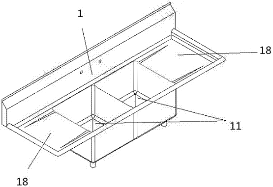
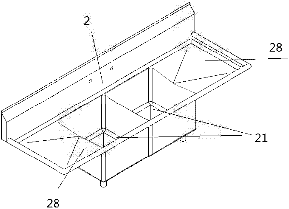
[0029] like image 3 As shown, a tank 2 includes two tank buckets 21 and two tank fins 28, each tank bucket 21 is welded to a tank fin 28.

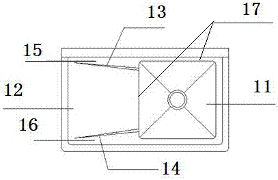
[0030] like Figure 4 As shown, a connection structure between a water tank and a tank fin includes a tank bucket 21 and a tank fin. There are first bead 13 and second bead 24, and the first bead 23 and the second bead 24 divide the water tank fin into three parts: the first area 22 of the water tank fin, the second area 25 of the water tank fin and the second area of ​​the water tank fin. Three areas 26, the first area 22 of the water tank fin is located between the second area 25 of the water tank fin and the third area 26 of the water tank fin, there is an intersection point or intersection at one end of the first bead 23 and one end of the second bead 24, the intersection point or The junction is located at the welding area 27 . The first...


PUM


Abstract

The invention relates to a water channel fin welding structure and a welding method. A connecting part between each water channel fin and a corresponding water channel hopper is a welding area (27). Each water channel fin is divided into three parts, namely a water channel fin first area (22), a water channel fin second area (25) and a water channel fin third area (26) through a first pressing rib (23) and a second pressing rib (24), wherein the water channel fin first area (22) is located between the water channel fin second area (25) and the water channel fin third area (26), one end of the first pressing rib (23) and one end of the second pressing rib (24) have an intersection point or an intersection position, and the intersection point or the intersection position is located in the corresponding welding area (27). By means of the water channel fin welding structure and the welding method, the coinciding section of one area of each water channel fin and the corresponding welding area is limited to be the minimum through the corresponding pressing ribs so that heat generated during welding can only cause deformation changes of the corresponding two areas beside, the deformation degree of each middle area is the minimum and can be ignored, and therefore a slope structure of each middle area cannot be damaged, and it is ensured that accumulated water can flow into a water channel from the middle areas.

Description

technical field [0001] The invention relates to a welding structure and a welding method of a water tank and a water tank fin. Background technique [0002] Stainless steel sinks have been popular for a long time, and more stainless steel sinks are used. This choice is not only because the metal texture of stainless steel is quite modern, but more importantly, stainless steel is easy to clean, the panel is thin and light, and it is also corrosion-resistant. , high temperature resistance, moisture resistance and other advantages. [0003] Usually, the stainless steel water tank needs to be welded with the water tank fin, and the water tank fin is set at an inclined angle, so that the water accumulated on it can flow into the water tank from high to low along the slope. However, a large amount of harmful heat will be generated during the welding process of the stainless steel tank and the tank fin, which will cause the tank fin to deform and form an uneven structure. Water a...

Claims


Application Information

Patent Timeline
Patent Type & Authority Patents(China)
IPC IPC(8): B23K37/00B23K101/12
CPCB23K37/00B23K2101/12
Inventor 周世春王庭焰夏权盛程唐旺
Owner 宁波聚利金属制品有限公司
Why Eureka
Try Eureka