Pipeline type pollutant treatment device capable of switching double flow channels

A pollutant treatment and pipeline-type technology, which is applied in the aviation field, can solve problems such as waste, achieve low flow resistance characteristics and pollutant control, and take into account the effect of flow resistance characteristics and pollutant control

Pending Publication Date: 2021-03-26
COMAC +1
View PDF14 Cites 0 Cited by
  • Summary
  • Abstract
  • Description
  • Claims
  • Application Information

AI Technical Summary

Problems solved by technology

[0003] For these non-sustained pollution sources, if only pollutant treatment devices are installed in the environmental control system (generally by means of filtration or adsorption), it will inevitably increase the system flow resistance under all working conditions, resulting in waste

Method used


Image

  • Pipeline type pollutant treatment device capable of switching double flow channels
  • Pipeline type pollutant treatment device capable of switching double flow channels

Examples


Embodiment Construction

[0038] Specific implementations of the present invention will be described below. It should be noted that in the process of specific descriptions of these implementations, for the sake of concise description, it is impossible for this specification to describe all the features of the actual implementations in detail. It should be understood that, in the actual implementation process of any embodiment, just like in the process of any engineering project or design project, in order to achieve the developer's specific goals and to meet system-related or business-related constraints, Often a variety of specific decisions are made, and this can vary from one implementation to another. In addition, it will be appreciated that while such development efforts may be complex and lengthy, the technology disclosed in this disclosure will be Some design, manufacturing or production changes based on the content are just conventional technical means, and should not be interpreted as insuffic...


PUM


Abstract

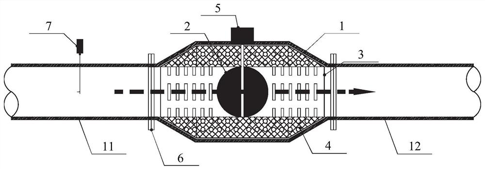
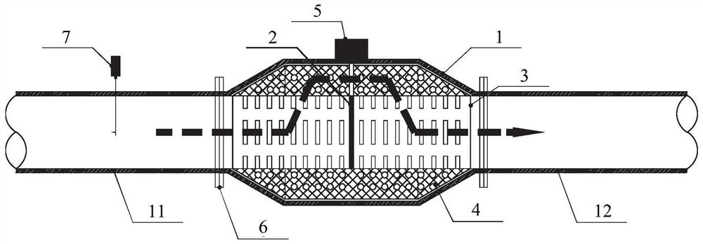
The invention relates to a double-channel switching pipeline type pollutant treatment device. The double-flow-channel switching pipeline type pollutant treatment device comprises a central flow channel and a peripheral flow channel, the central flow channel is located in the center of the pipeline type pollutant treatment device, a valve element used for achieving on-off of the central flow channel is installed in the central flow channel, the peripheral flow channel is nested outside the central flow channel, and the central flow channel is communicated with the peripheral flow channel. A filter material is arranged in the peripheral flow channel, and the central flow channel and the peripheral flow channel are separated by a cylindrical grid plate. According to the technical scheme, themethod has the beneficial technical effect that the low flow resistance characteristic and pollutant control under different upstream pollution states are both considered.

Description

technical field [0001] The invention relates to the field of aviation technology, in particular to a pipeline-type pollutant treatment device with double-channel switching. Background technique [0002] The air source of the traditional civil aircraft environmental control system comes from the engine bleed air, and the quality of the bleed air will directly affect the quality of the air sent downstream to the cabin. However, there are many types of pollutants in the bleed air, and the pollution sources are non-continuous, and there will be great differences with different flight stages. For example, fuel vapor or lubricating oil vapor will escape to the air inlet when the engine is just started or shut down, but it is difficult to occur under other working conditions; atmospheric pollution from outside the cabin, such as PM2.5, PM10, nitrogen oxides, etc., will When waiting on the ground, it is sucked into the bleed port with the engine, and the content of these substances...

Claims


Application Information

Patent Timeline
IPC IPC(8): B64D13/06
CPCB64D13/06B64D2013/0651
Inventor 张絮涵程湛刘毓迪彭全闵智勇吴成云
Owner COMAC
Why Eureka
Try Eureka