Photobioreactor systems and methods for treating CO2-enriched gas and producing biomass

a photobioreactor and co2 flue gas technology, applied in the field of photobioreactors, can solve the problems of inability to meet the needs inability to meet the needs of biofuel production, and inability to capture carbon dioxide from flue gas of anthropogenic sources such as electric power plants, etc., to achieve the effect of facilitating evaporative cooling of liquid medium

Inactive Publication Date: 2008-07-31
THE TRON GRP
View PDF98 Cites 146 Cited by
  • Summary
  • Abstract
  • Description
  • Claims
  • Application Information

AI Technical Summary

Benefits of technology

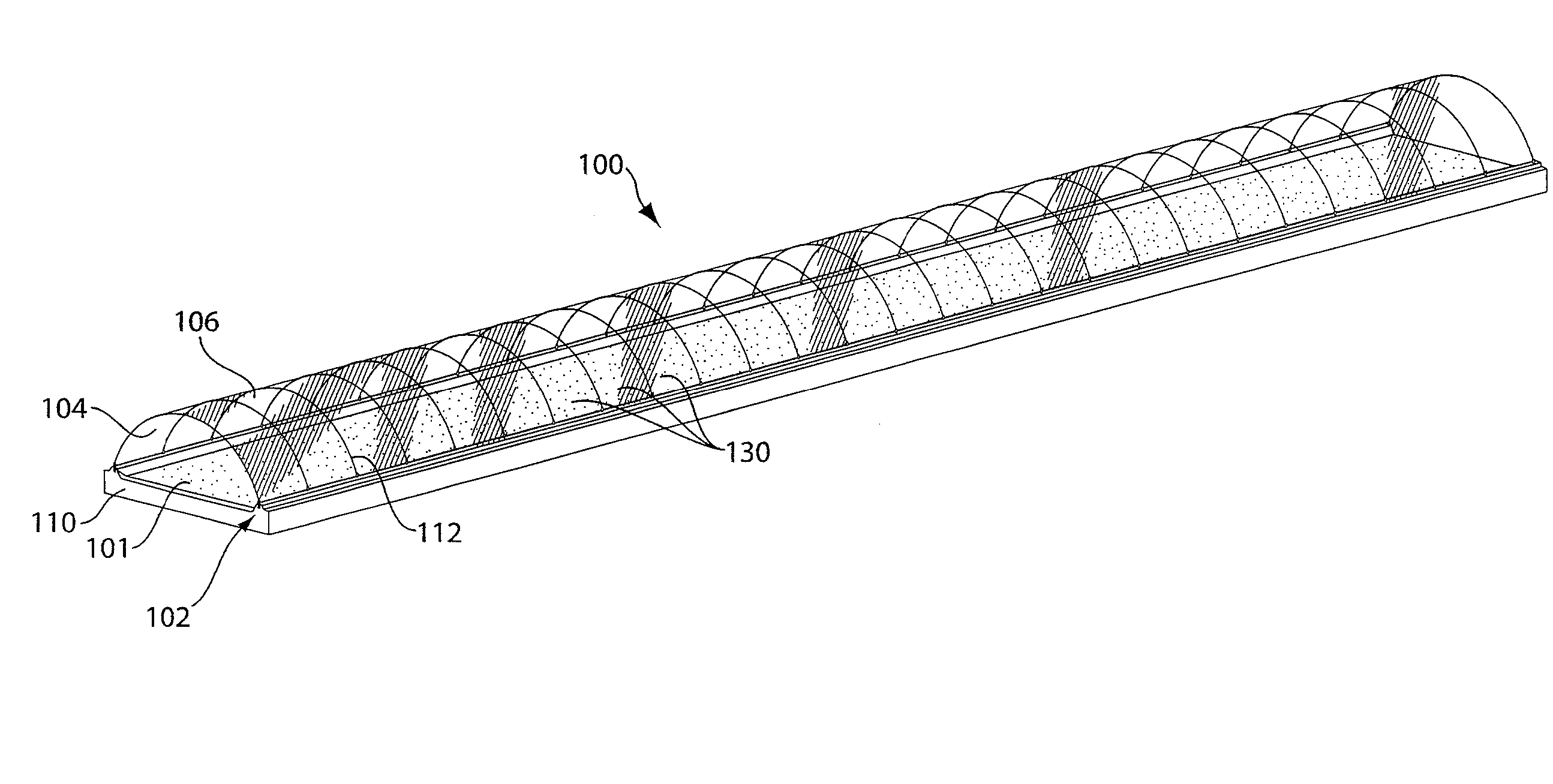
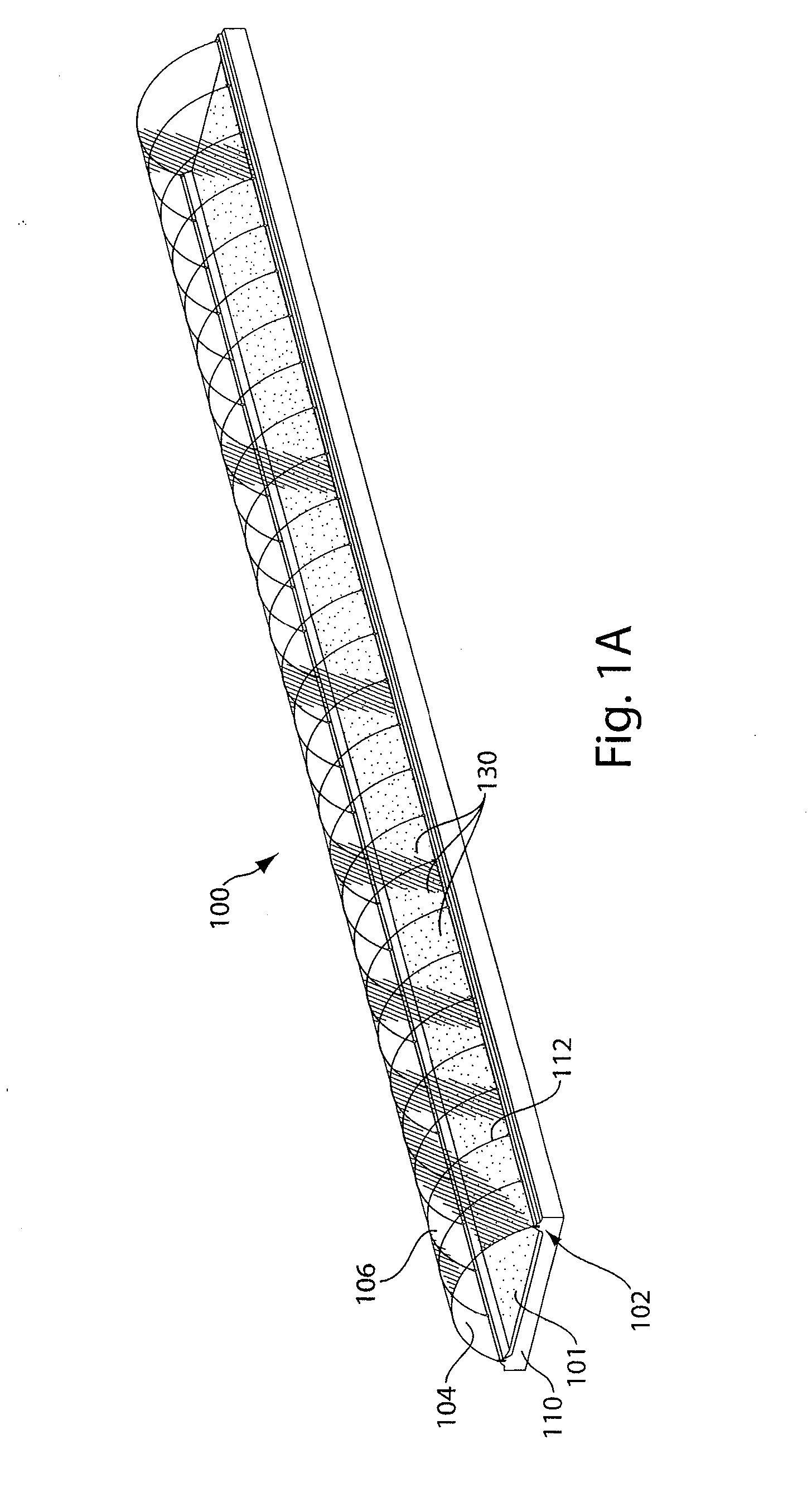
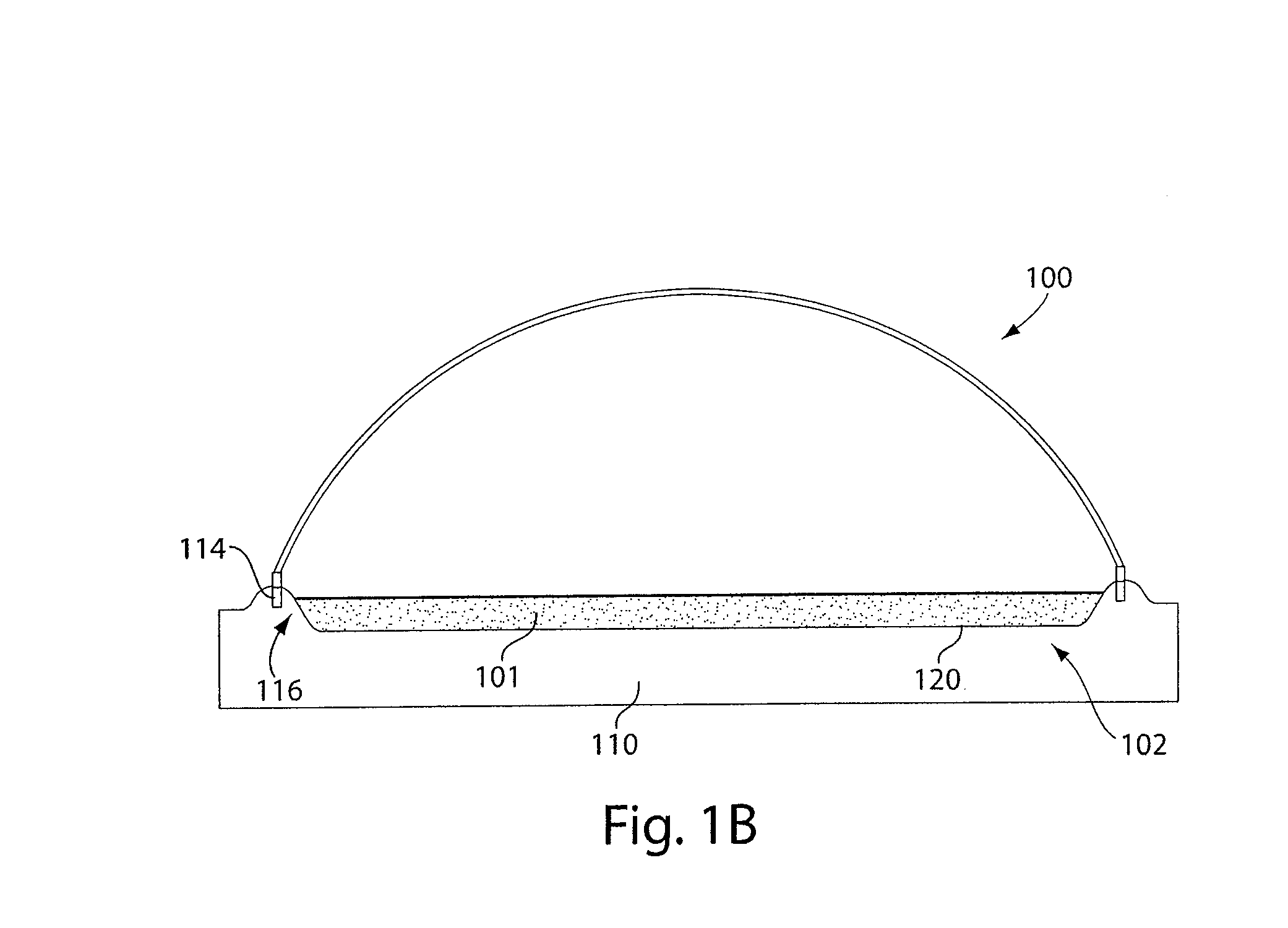
[0028]According to a further embodiment of the invention, a photobioreactor system capable of supporting the growth of phototrophic organisms using a gas containing an elevated concentration of carbon dioxide comprises at least one photobioreactor section constructed and arranged to carry a flow of liquid medium comprising phototrophic organisms therein. The photobioreactor section comprises a cover constructed and arranged to cover at least a substantial portion of the liquid medium within the photobioreactor section and constructed and arranged to provide a gas headspace under the cover and above the liquid medium, the gas headspace being maintainable at a pressure that differs from atmospheric pressure. The photobioreactor section further comprises a liquid inlet configured to provide liquid medium to the photobioreactor section, a liquid outlet from which liquid medium is removable from the photobioreactor section, and a gas outlet from which gas containing carbon dioxide at a concentration less than at the gas inlet is removable from the photobioreactor section. The photobioreactor section comprises a first portion of the photobioreactor section in which the cover provides the gas headspace over a first portion of the liquid medium, and further comprises a second, different portion of the photobioreactor section in which a second portion of the liquid medium is exposed to gas outside of the gas headspace to facilitate evaporative cooling of the liquid medium.

Problems solved by technology

Many biofuels meet renewable energy source standards, however, sources of conventional biofuels, such as biomass, biodiesel, and bioethanol, are not uniformly geographically distributed across the nation, and in general, these sources are not located close to power generation facilities.
Typically, capturing carbon dioxide from the flue gas of anthropogenic sources such as electric power plants is expensive.
In addition, algae are capable of growing in saline waters that are unsuitable for agriculture.
Each program took a different approach, but because of various problems addressed by certain embodiments of the present invention, none has been commercially successful to date.
A major obstacle for feasible algal bio-regeneration and pollution abatement has been an efficient, yet cost-effective, growth system.
The ponds require low capital input; however, algae grown in open and uncontrolled environments result in low algal productivity.
The open pond technology made growing and harvesting the algae prohibitively expensive, because massive amounts of dilute algal waters required very large agitators, pumps and centrifuges.
Furthermore, with low algal productivity and large flatland requirements, this approach could, in the best-case scenario, be applicable to only 1% of U.S. power plants.
On the other hand, the MITI approach, with stricter land constraints, focused on very expensive closed algal photobioreactors utilizing fiber optics for light transmission.
In these controlled environments, much higher algal productivity was achieved, but the algal growth rates were not high enough to offset the capital costs of the systems utilized.

Method used


Image

  • Photobioreactor systems and methods for treating CO2-enriched gas and producing biomass
  • Photobioreactor systems and methods for treating CO2-enriched gas and producing biomass
  • Photobioreactor systems and methods for treating CO2-enriched gas and producing biomass

Examples


example 1

[0132]In this example, a laboratory test of an embodiment of a photobioreactor of the present disclosure is compared to a model of the same. Algae species Nannochloris sp. is grown in a 20 cm depth of Media 1, which is sea water comprising 0.075 g / l NaNO3 and 0.00565 g / l NaH2PO4.2H2O. The growth rates for the algae as a function of time, concentration, and light intensity, measured as photon flux, can be derived from laboratory tests with well-stirred open tanks fed with gas containing 5 mol % CO2 and the balance O2 and N2 in a 1:5 molar ratio. The test results are shown in FIG. 19 for insolation rates of 2000, 1000, and 750 μE / m2·s, and the productivity is tabulated in Table 1. As shown in FIG. 8, the productivity is not a function of concentration in this operating range. Independently, the growth rate can be predicted following the methods of Wu and Merchuk, (A Model Integrating Fluid Dynamics in Photosynthesis and Photoinhibition Processes. Chemical Engineering Science 56:3527-3...

example 2

[0135]This example illustrates the advantage of embodiments of photobioreactors disclosed herein compared to a conventional raceway pond. The reactor productivity, CO2 conversion, power requirements for the flue gas handling, and water consumption are listed in Table 3 for the highest level of solar insolence using the same operating conditions of Example 1, based on published values for CO2 conversion and evaporation rates. Flue gas is sparged into a 2-meter deep well in the raceway via a blower that compresses flue gas to 8 psig. The results show that the hybrid bioreactor achieves comparable growth rates, while attaining greater CO2 conversion and using substantially less power. The raceway pond power consumption is significantly higher due to its lower CO2 capture efficiency, requiring higher flue gas flows per unit of algae produced, and its higher pressure drop. Water consumption for both reactors is comparable because both use evaporative cooling to maintain reactor temperatu...

example 3

[0136]This example illustrates the advantage of the hybrid open / closed bioreactor at a lower ambient temperature, 5° C., compared to a raceway pond. The system of Examples 1 and 2 is operated at identical conditions, with the exception that none of the recycled media of Example 1 is directed towards the cooling zone, and low-level heat from the power plant condenser cooling loop is used to maintain the bioreactor temperature. Table 3 lists the productivity and heat duty for maintaining 25° C. in the two reactors. The results show that this reactor has significant advantages over an open raceway pond.

TABLE 3Comparison of Bioreactor Performance at 5° C. AmbientLightReactorIntensityproductivityHeat dutyExample(μE / m2-s)(g / m2-hr)(kW / m2)Example 3 -10001.10.02PhotobioreactorExample 3 -10001.10.10Raceway pond


PUM

PropertyMeasurementUnit
gas pressure dropaaaaaaaaaa
wavelengthaaaaaaaaaa
lengthaaaaaaaaaa

Abstract

Certain embodiments and aspects of the present invention relate to a photobioreactor including covered photobioreactor units through which a liquid medium stream and a gas stream flow. The liquid medium comprises at least one species of phototrophic organism therein. Certain methods of using the photobioreactor system as part of fuel generation system and / or a gas-treatment process or system at least partially remove certain undesirable pollutants from a gas stream. In certain embodiments, a portion of the liquid medium is diverted from a photobioreactor unit and reintroduced upstream of the diversion position. In certain embodiments, the disclosed photobioreactor system, methods of using such systems, and / or gas treatment apparatus and methods provided herein can be used as part of an integrated combustion method and system, wherein photosynthetic organisms used within the photobioreactor are harvested from the photobioreactor, processed, and used as a fuel source for a combustion system such as an electric power plant.

Description

FIELD OF THE INVENTION[0001]The invention relates generally to photobioreactors and processes to operate and use photobioreactors for the treatment of gases, such as flue gases, and for the production of biomass.DISCUSSION OF THE RELATED ART[0002]The power generation industry is coming under increasing pressure to produce electricity from renewable energy sources. Many biofuels meet renewable energy source standards, however, sources of conventional biofuels, such as biomass, biodiesel, and bioethanol, are not uniformly geographically distributed across the nation, and in general, these sources are not located close to power generation facilities.[0003]At the same time, reductions in carbon dioxide emissions and other gas emissions from various sources are becoming increasingly necessary and / or desirable. Typically, capturing carbon dioxide from the flue gas of anthropogenic sources such as electric power plants is expensive.[0004]Photosynthesis is the carbon recycling mechanism of ...

Claims


Application Information

Patent Timeline
Patent Type & Authority Applications(United States)
IPC IPC(8): C12N1/12C12M1/00C12M1/38B01D53/62B01D53/96C02F3/00
CPCB01D53/84B01D2251/95B01D2257/504C02F3/32C02F2103/18Y02C10/04C12M23/56C12M43/04C12N1/12Y02C10/02C12M21/02Y02W10/37Y02P20/59Y02A50/20Y02C20/40Y02P60/20
Inventor LEWNARD, JOHN J.WU, XIAOXI
Owner THE TRON GRP
Why Eureka
Try Eureka