Novel decelerator

A reducer, a new type of technology, applied in mechanical equipment, transmission parts, gear transmission and other directions, can solve the problem of radial runout of transmission wheels

Inactive Publication Date: 2015-05-27
XIAN DAYU PHOTOELECTRIC TECH
View PDF0 Cites 4 Cited by
  • Summary
  • Abstract
  • Description
  • Claims
  • Application Information

AI Technical Summary

Problems solved by technology

But such a simple transmission structure also has its disadvantages. Since only the transmission shaft supports the transmission wheel in the reduction box as a unilateral shaft, when th...

Method used


Image

  • Novel decelerator

Examples


Embodiment Construction

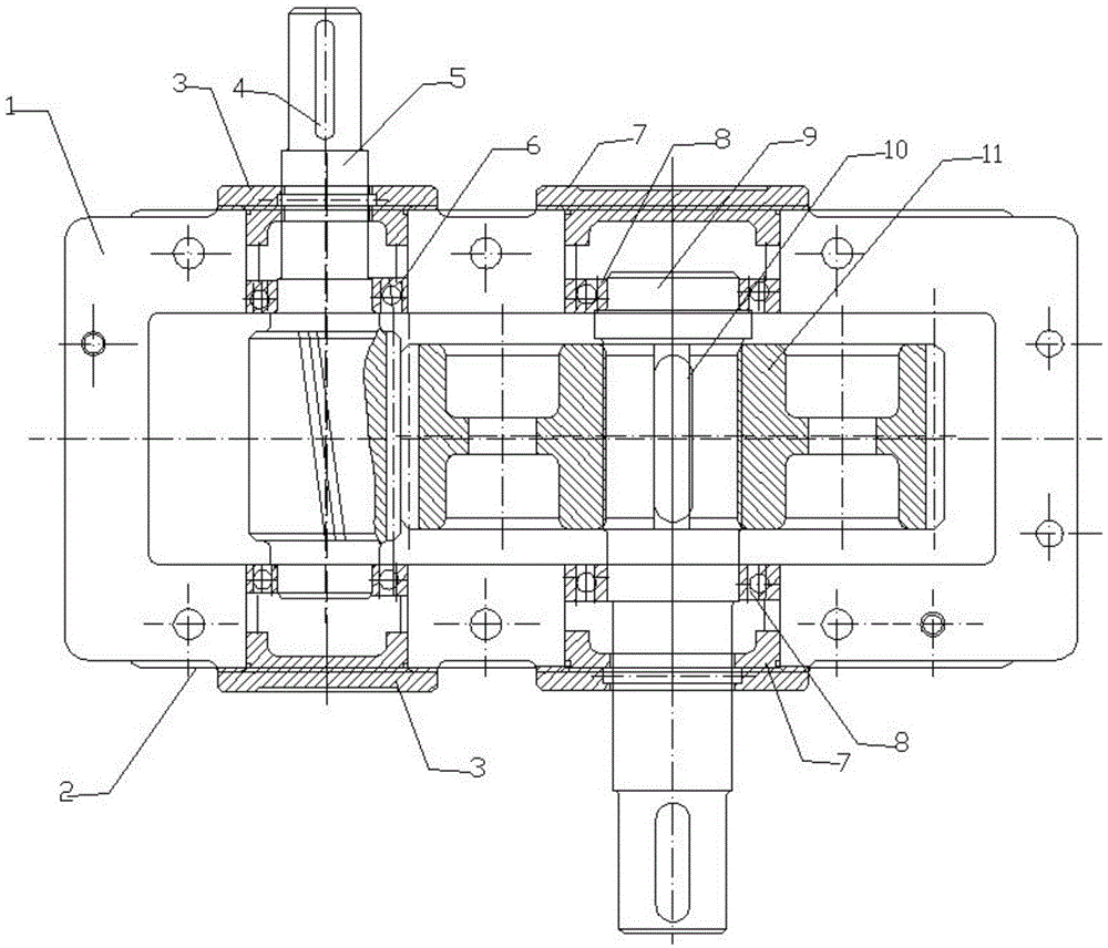
[0008] The present invention will be described in further detail below in conjunction with the accompanying drawings.

[0009] Referring to the accompanying drawings, a new type of reducer includes a housing 1, a small shaft bearing 6 is arranged at each end of a small shaft 5, and is supported on the housing 1, and a large shaft bearing 8 is arranged at each end of a large shaft 9, It is supported on the housing 1, and each protruding end has a keyway, and the small key 4 and the large key 10 are connected with the external motor and the working mechanism for positioning, and the two ends of the small shaft 5 and the large shaft 9 pass through the small shaft end cover 3 Seal it with the large shaft end cover 7 and the sealing ring to prevent dust from entering. The middle part of the small shaft 5 is provided with a gear to mesh with the large reduction gear 11. The extended end of the small shaft 5 is equipped with a motor, and the extended end of the large shaft 9 The outp...


PUM


Abstract

Disclosed is a novel decelerator. The novel decelerator comprises a housing, wherein two small shaft bearings are respectively arranged at two ends of a small shaft, and support the small shaft on the housing, two large shaft bearings are respectively arranged at two ends of a large shaft, and support the large shaft on the housing, key grooves are formed in stretching ends of the small shaft and the large shaft, the small shaft and the large shaft are positioned by being connected with an external motor and a work mechanism through small keys and large keys, the two ends of the small shaft and the two ends of the large shaft are sealed through small shaft covers, large shaft covers and seal rings, a gear is arranged in the middle of the small shaft and meshed with a large deceleration gear, a motor is installed at the stretching end of the small shaft, and the stretching end of the large shaft is used as an output shaft. The work mechanism is installed on the novel decelerator, and therefore radial jumping of a transmission shaft portion in a deceleration box and a transmission wheel supported by the transmission shaft portion can be effectively reduced, and furthermore the novel decelerator has the advantage of being reasonable in structure.

Description

technical field [0001] The invention relates to a speed reducer, in particular to a novel speed reducer. Background technique [0002] As a kind of intermediate transmission equipment, the reduction box is mostly composed of gears and shafts in the internal transmission system. For some small reduction boxes, the internal transmission system is relatively simple, and some may only have two-stage transmission, that is, the main engine inputs the transmission torque to the reduction box, and the reduction box performs a speed adjustment, and then outputs to the terminal equipment. In this kind of simple transmission process, the internal structure is mostly relatively simple, and the transmission shaft of the reduction box often not only undertakes the transmission function, but also bears the supporting role for the transmission wheel in the reduction box. But such a simple transmission structure also has its disadvantages. Since only the transmission shaft supports the tran...

Claims


Application Information

Patent Timeline
IPC IPC(8): F16H1/04F16H57/021
CPCF16H1/06F16H57/021F16H57/023F16H2057/02034
Inventor 张超
Owner XIAN DAYU PHOTOELECTRIC TECH
Why Eureka
Try Eureka