Air expansion shaft driving device

A driving device and an inflatable shaft technology, which is applied in the combination of couplings and brakes, transportation and packaging, and coiling of strips, etc. It can solve the problems of increased runout of the inflatable shaft and difficulty in ensuring the coaxiality of the rotating mechanism, etc. , to achieve the effect of reducing radial runout, low manufacturing cost and good device accuracy

Inactive Publication Date: 2011-04-13
苏州高新区禾云设备设计事务所
View PDF6 Cites 5 Cited by
  • Summary
  • Abstract
  • Description
  • Claims
  • Application Information

AI Technical Summary

Problems solved by technology

[0003] At present, the driving end of the inflatable shaft is fixed on a rotating mechanism, and the coaxiality of the rotating mechanism itself is difficult to guarantee
In addition, in order to facilitate the clamping of the inflatable shaft, there is a gap between the driving end of the inflatable shaft and the fixing of the rotating mechanism, resulting in increased jumping of the inflatable shaft

Method used


Image

  • Air expansion shaft driving device
  • Air expansion shaft driving device

Examples


Embodiment Construction

[0015] The technical implementation process of the present invention will be further described below in conjunction with the accompanying drawings and embodiments.

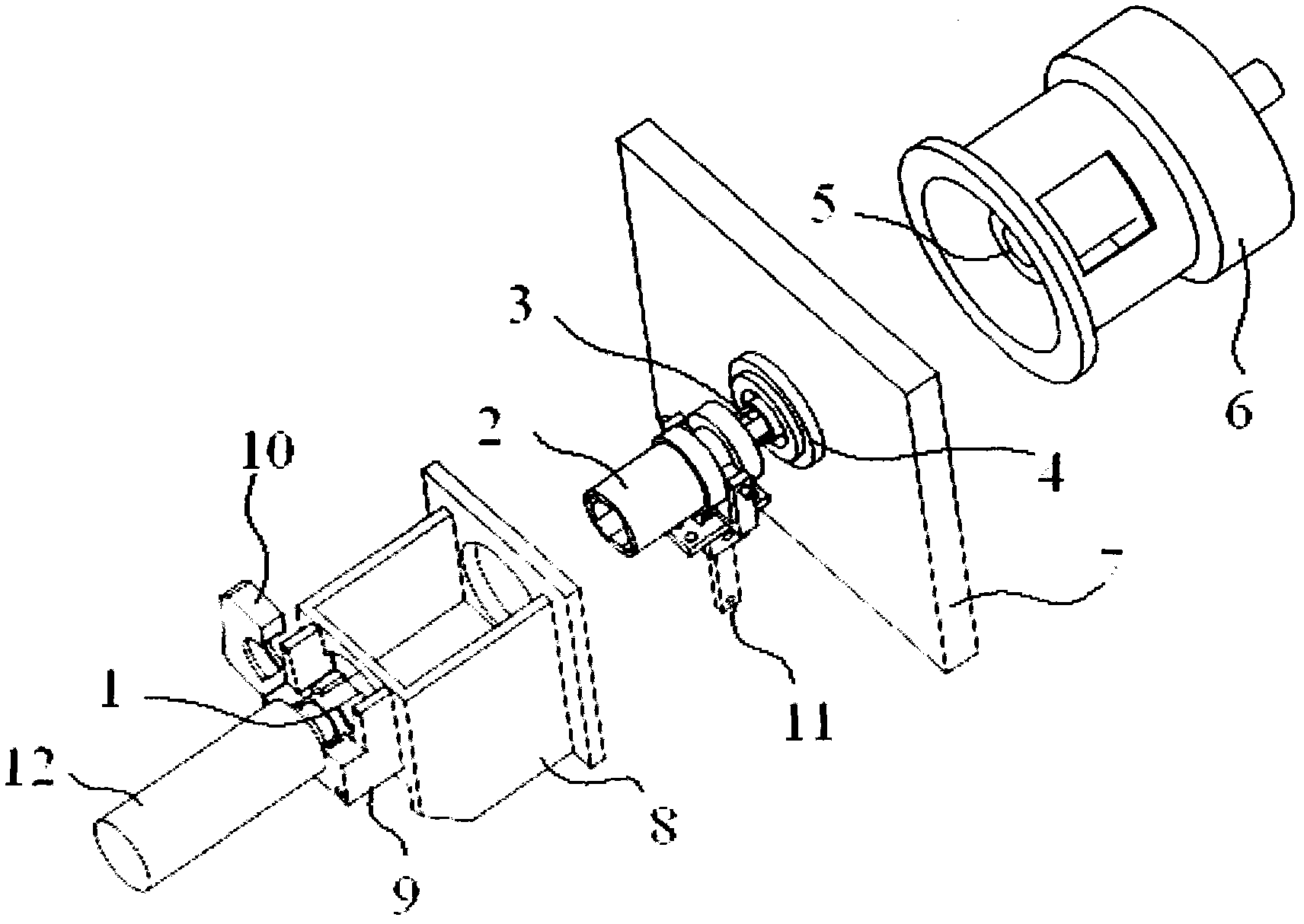
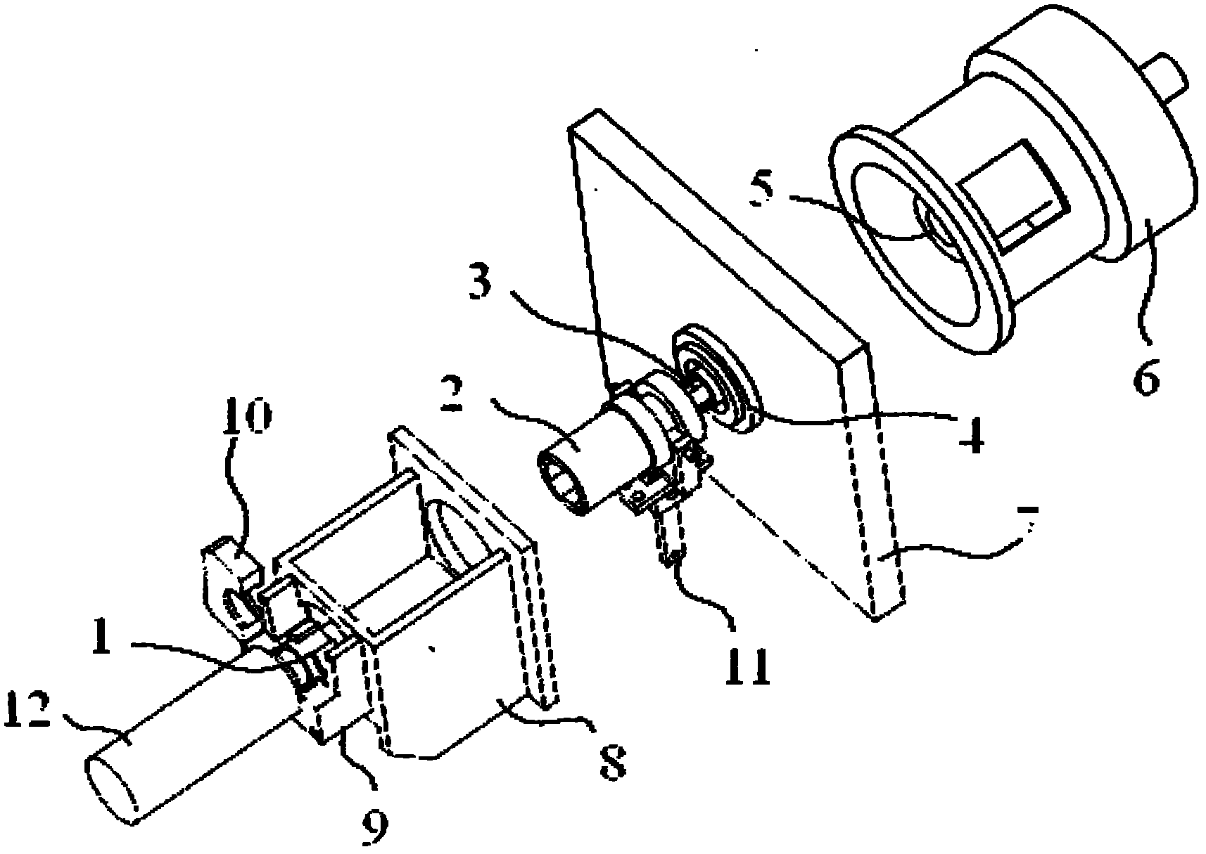
[0016] see figure 1 As shown, an inflatable shaft driving device includes an inflatable shaft spline 1 fixed at the end of the inflatable shaft 12, and the inflatable shaft spline 1 is connected to a clutch spline 2 through a shift fork 11. The clutch spline 2 is connected to the spline shaft 3, the spline shaft 3 is connected to a coupling 5 through a bearing seat 4, and the coupling 5 is arranged in a magnetic powder clutch brake 6.

[0017] Further, the bearing seat 4 is fixedly arranged on a fixed side plate 7 .

[0018] Further, the clutch spline 2 is installed in an air expansion shaft seat 8, the air expansion shaft bearing seat 9 is fixed on the air expansion shaft seat 8, and the inner side of the air expansion shaft spline 1 is provided with a bearing, so Said bearing is arranged in said air expansion ...


PUM


Abstract

The invention discloses an air expansion shaft driving device. The air expansion shaft driving device comprises an air expansion shaft spline which is fixed at the end part of the air expansion shaft, wherein the air expansion shaft spline is in contact connection with a clutch spline through a shifting fork; the clutch spline is connected to a spline shaft; the spline shaft is connected with a shaft coupler through a bearing pedestal; the shaft coupler is arranged in a magnetic powder clutch brake; and the magnetic powder clutch brake provides driving. A bearing is directly arranged on an air expansion shaft, so the air expansion shaft driving device greatly reduces the radial runout during the operation of the air expansion shaft and greatly improves the rolling performance of a splitting machine.

Description

technical field [0001] The invention belongs to a slitting machine, and in particular relates to an air expansion shaft driving device of a slitting machine. Background technique [0002] The inflatable shaft must be dynamically parallel to the front guide roller during operation, so that the winding material can be wound smoothly and wrinkle-free. [0003] At present, the driving end of the inflatable shaft is fixed on a rotating mechanism, and it is difficult to guarantee the coaxiality of the rotating mechanism itself when it rotates. In addition, in order to facilitate the clamping of the inflatable shaft, there is a gap between the driving end of the inflatable shaft and the fixing of the rotating mechanism, resulting in increased jumping of the inflatable shaft. Contents of the invention [0004] In order to overcome the deficiencies in the prior art, the object of the present invention is to provide an inflatable shaft driving device with greatly reduced radial run...

Claims


Application Information

Patent Timeline
Patent Type & Authority Applications(China)
IPC IPC(8): B65H18/10B65H35/00F16D67/02
Inventor 张晓鹤
Owner 苏州高新区禾云设备设计事务所
Why Eureka
Try Eureka