Eureka AIR delivers breakthrough ideas for toughest innovation challenges, trusted by R&D personnel around the world.

Turning clamp and turning method of polycrystalline rod material

A polycrystalline bar material and turning technology, which is applied in the direction of manufacturing tools, fine working devices, and working accessories, can solve problems such as irregular geometric shapes and failure to meet process requirements, and achieve high safety, stable clamping, and The effect of small radial runout

Inactive Publication Date: 2013-12-11
TIANJIN HUANOU SEMICON MATERIAL TECH CO LTD
View PDF10 Cites 4 Cited by
  • Summary
  • Abstract
  • Description
  • Claims
  • Application Information

AI Technical Summary

Problems solved by technology

[0004] In view of the deficiencies in the prior art, the present invention provides a polycrystalline bar turning jig and turning method, which adopts a newly designed jig and a new processing method to solve the problem that polycrystalline bar is prone to geometrical irregularities during processing. Rules, problems that cannot meet the process requirements, in order to meet the processing accuracy requirements for raw materials

Method used


Image

  • Turning clamp and turning method of polycrystalline rod material
  • Turning clamp and turning method of polycrystalline rod material
  • Turning clamp and turning method of polycrystalline rod material

Examples


Embodiment Construction

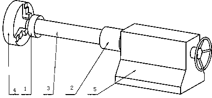
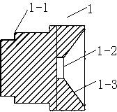
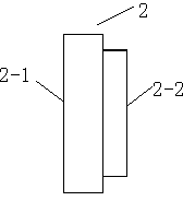
[0014] Such as figure 2 , 3 As shown, a polycrystalline bar turning fixture, the fixture includes a left end fixed plate 1, a right end fixed plate 2, the left end fixed plate 1 is a cylinder, one end of which is stepped 1-1, and the bottom end of the hole at the other end is a blind hole 1-2, the upper end in the hole is an inner cone surface 1-3, and the fixed disk 2 at the right end is a cylinder, one end of which is a plane 2-1, and the other end is a circular convex surface 2-2.

[0015] Such as figure 1 Shown, a kind of turning method step of polycrystalline bar stock is as follows:

[0016] Grind the left end of the polycrystalline rod 3 into a certain taper according to the size, cut the right end of the polycrystalline rod 3 into a plane, and the perpendicularity between the end surface and the center line of the polycrystalline rod 3 is less than 0.2mm, and then cut the polycrystalline rod 3 The right end face of the right end is glued together with the plane 2-1...


PUM


Abstract

The invention relates to a turning clamp and turning method of a polycrystalline rod material. A left end fixing disk is a cylinder, one end of the left end fixing disk is a step shape, a blind hole is formed in the bottom end of the interior of a hole in the other end of the left end fixing disk, the upper end of the interior of the hole in the other end of the left end fixing disk is an inner conical surface, a right end fixing disk is a cylinder, one end of the right end fixing disk is a plane, and the other end of the right end fixing disk is a round protruding surface. The turning method of the polycrystalline rod material comprises the steps that a three-jaw chuck at the left end of a lathe is used for fixedly clamping the left end fixing disk with the inner conical surface, the left end fixing disk is used for fixing one side, with a conical surface, of the polycrystalline rod material in the process of machining, the end face of the other side of the polycrystalline rod material bonds with the right end fixing disk, a center of a tailstock of the lathe is used for carrying out centering abutting operation, a hard alloy tool is tightly clamped, after tool setting is accomplished, turning of the polycrystalline rod material is carried out according to preferable technological parameters which include that the cutting speed is 94m / min, the longitudinal feed ratio is 0.2, the amount of feed is 2mm and the angle of feed is 80 degrees, meanwhile, a dust removal and cooling device is started, and inspection is carried out according to the requirement for machining accuracy after turning is accomplished. The turning clamp and turning method of the polycrystalline rod material are stable in clamping, low in radial runout and high in safety, and improve machining efficiency and the product percent of pass.

Description

technical field [0001] The invention relates to the field of machining and preparing materials for polycrystalline silicon rods in the semiconductor industry, in particular to a turning fixture and a turning method for polycrystalline silicon rods. Background technique [0002] The processing of polycrystalline rods is to provide raw materials for pulling single crystals, and there are strict dimensional requirements for the geometry of the processed rods. Bars with irregular geometric shapes often cause problems during crystal pulling, which is not conducive to the automatic growth of crystals. [0003] At present, imported abrasive belt machines are generally used in the industry to process polycrystalline bars. Although they can guarantee better processing accuracy, the purchase cost is high and the processing efficiency is low. There is no special turning machine tool for polycrystalline bar at home and abroad, and the corresponding technical transformation of the exist...

Claims


Application Information

Patent Timeline
IPC IPC(8): B28D7/04B28D7/02B28D5/02
Inventor 靳立辉于书翰贾弘源刘旭光闫耀东卢君姚长娟李立伟杨春庚
Owner TIANJIN HUANOU SEMICON MATERIAL TECH CO LTD
Why Eureka
Eureka Blog
Learn More