Multi-functional lighter
A lighter and multi-functional technology, applied in the direction of combustion ignition, igniter with fuel, optics, etc., can solve the problems of lighter fuel storage volume conflicts, etc., and achieve good amplification effect
- Summary
- Abstract
- Description
- Claims
- Application Information
AI Technical Summary
Problems solved by technology
Method used
Image
Examples
Embodiment 1
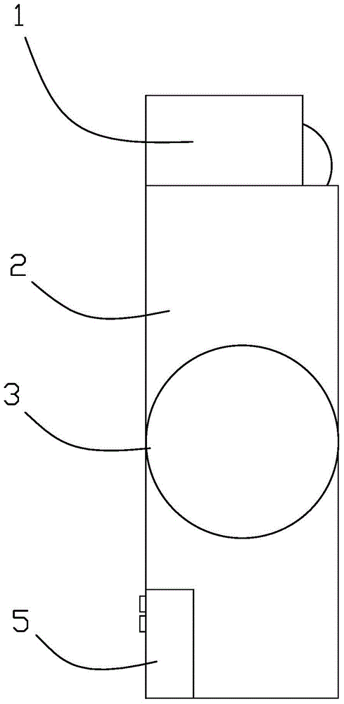
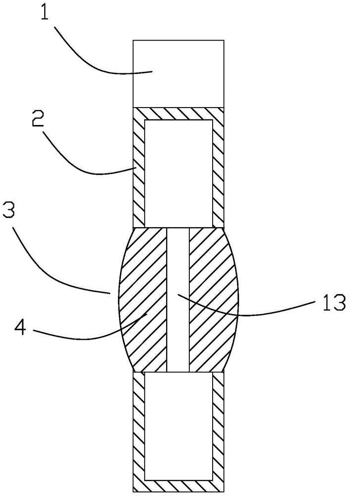
[0022] A kind of multifunctional lighter of present embodiment, as figure 1 As shown, it includes a lighter head 1 and a fuel storage case 2, and the lighter head is installed on the upper part of the fuel storage case. A magnifying glass mechanism 3 is arranged in the middle part of the fuel storage case, and the magnifying glass mechanism is circular, and is cut and arranged in the middle of the fuel storage case, and the fuel storage case is separated into upper and lower parts. Such as figure 2 As shown, the magnifying glass mechanism is made up of two semi-convex mirrors 4, the semi-convex mirror is circular, one side is convex in the center, and the other side is a plane, and the two semi-convex mirrors are arranged opposite to each other with a flat side, and the two semi-convex mirrors A gap is provided between them to form a flow cavity 13, which communicates with the inner cavity of the fuel storage shell, and two semi-convex mirrors together form a convex lens str...
Embodiment 2
[0025] Such as Figure 5 As shown, the second structure of the multifunctional lighter is given, including a lighter head 1 and a fuel storage case 2, and the lighter head is installed on the upper part of the fuel storage case. A magnifying glass mechanism 3 is arranged on the fuel storage case, and the magnifying glass mechanism is arranged in the middle of the fuel storage case. The convex mirror is circular, one side is convex in the center, and the other side is a plane. Two semi-convex mirrors are arranged opposite to each other with a plane side. A gap is arranged between the two semi-convex mirrors to form a flow cavity 13. The flow cavity and the inside of the fuel storage shell The cavities are connected. Other structures of the lighter in this embodiment are the same as those in Embodiment 1, and will not be repeated here.
Embodiment 3
[0027] Such as Image 6 As shown, the third structure of the multifunctional lighter is given, including a lighter head 1 and a fuel storage case 2, and the lighter head is installed on the upper part of the fuel storage case. A magnifying glass mechanism 3 is arranged on the fuel storage case, and the magnifying glass mechanism is circular and is arranged on the lower part of the fuel storage case, such as Figure 7 As shown, the magnifying glass mechanism may also be located at the bottom of the fuel storage case. The magnifying glass mechanism is made up of two half-convex mirrors 4, and this half-convex mirror is circular, and one side is a center convex, and the other side is a plane, and the two half-convex mirrors are arranged oppositely with a flat side, and a gap is arranged between the two half-convex mirrors. The gap forms a flow cavity 13, which communicates with the internal cavity of the fuel storage shell. Other structures of the lighter in this embodiment are...
PUM
 Abstract
Description
Claims
Application Information
 - R&D
- Intellectual Property
- Life Sciences
- Materials
- Tech Scout
- Unparalleled Data Quality
- Higher Quality Content
- 60% Fewer Hallucinations
Browse by: Latest US Patents, China's latest patents, Technical Efficacy Thesaurus, Application Domain, Technology Topic, Popular Technical Reports.
© 2025 PatSnap. All rights reserved.Legal|Privacy policy|Modern Slavery Act Transparency Statement|Sitemap|About US| Contact US: help@patsnap.com


