Preparation method of LED light-emitting device, and LED light-emitting device

A light-emitting device, LED chip technology, applied in semiconductor devices, optics, instruments, etc., can solve the problems of thinning difficulties, low production efficiency, and high process requirements, and achieve low production costs, high production efficiency, and high tolerance. Effect

Inactive Publication Date: 2021-01-22
苏州东岩电子科技有限公司
View PDF5 Cites 5 Cited by
  • Summary
  • Abstract
  • Description
  • Claims
  • Application Information

AI Technical Summary

Problems solved by technology

[0003] The direct-type backlight module generally includes from bottom to top: backplane, LED backlight, diffusion plate, and other optical films. The LED backlight includes multiple LED light-emitting devices. Light-emitting devices include: LED strips, Miniled backlight boards, etc. Since the direct-type backlight module uses the light emitted by the LED backlight to directly illuminate the screen, that is, the light is directly scattered, so the required height of mixed light is relatively high, resulting in direct-type backlight modules. The thickness of the backlight module is greater than that of the side-type backlight module, and it has always been difficult to achieve slimming
[0004] LED light-emitting devices are generally composed of substrates and LED particles. In order to pursue the thinning of direct-lit backlight modules, LED light-emitting devices will mount lenses on top of LED particles. However, the traditional process of mounting lenses is to use SMT chips. The method of pasting the lens on the top of the LED particles has high requirements on the process, the output per unit time is too small, the production efficiency is low, and the cost is high.

Method used


Image

  • Preparation method of LED light-emitting device, and LED light-emitting device
  • Preparation method of LED light-emitting device, and LED light-emitting device
  • Preparation method of LED light-emitting device, and LED light-emitting device

Examples


Embodiment 1

[0052] A kind of preparation method of LED light-emitting device, such as Figure 1-Figure 7 shown, including steps:

[0053] S1, attaching the LED particles to the substrate of the LED light-emitting device;

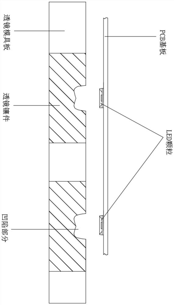
[0054] S2, filling the concave part of the lens insert on the lens mold plate with curing glue;

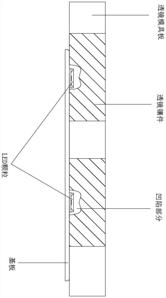
[0055] S3, inverting and pressing the substrate after step S1 onto the lens mold plate after step S2, the position of the LED particles corresponds to about the middle position of the concave part of the lens insert;

[0056] S4, curing the substrate and the lens mold plate pressed together after step S3, after the curing glue is cured, the curing glue, LED particles, and the substrate are fixed together, and after the mold is opened, an LED light-emitting device is obtained.

[0057] The lens formed after the curing glue is cured has only one optical surface. There are multiple concave parts of the lens insert, and the specific number and distribution of the concave par...

Embodiment 2

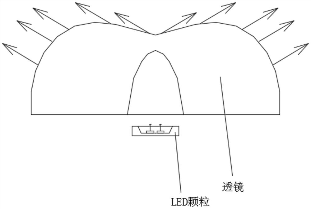
[0061] A kind of LED lighting device, such as Figure 4 with Figure 5 As shown, it includes: a substrate, LED particles, and a lens. The LED particles or LED chips are mounted on the substrate, and the lens is above the LED particles. It is characterized in that the LED particles are located at about the middle of the lens, and the lens There is only one optical surface, and the lens is directly molded by curing glue.

[0062] The shape of the lens is preferably: M shape, the curing glue is heat curing glue, and the substrate is a PCB substrate or an FPC substrate. When the substrate is an FPC substrate, a back plate is also provided under the FPC substrate. Curing glue fixes LED particles, FPC substrate and backplane together. There are multiple LED particles or LED chips, which are evenly distributed and mounted on the substrate in the form of rows and columns. LED particles include LED chips and brackets. LED chips include: blue LED chips, red LED chips, green LED chips,...


PUM

PropertyMeasurementUnit
reflectanceaaaaaaaaaa

Abstract

The invention provides a preparation method of an LED light-emitting device. The preparation method comprises the steps that S1, LED particles or LED chips are attached to a substrate of a LED light-emitting device; S2, the concave part of a lens insert on a lens mold plate is filled with a curing glue; S3, the substrate obtained in the step S1 is inversely pressed on the lens mold plate obtainedin the step S2, wherein the positions of the LED particles or the LED chips correspond to about the middle position of the concave part of the lens insert; and S4, the substrate and the lens mold plate which are pressed together in the step S3 are cured, after the curing glue is cured, the curing glue, the LED particles or the LED chips and the substrate are fixed together, and after mold opening,a LED light-emitting device is obtained. The invention further provides an LED light-emitting device, which is characterized in that LED particles or LED chips are located at the position about the middle of a lens, the lens is only provided with one optical face, and the lens is directly formed in a compression molding mode through a curing glue.

Description

technical field [0001] The present invention relates to the technical field of display devices, and more particularly, to a method for preparing an LED light emitting device and the LED light emitting device. Background technique [0002] The backlight modules of TV or computer display devices are divided into side-type backlight modules and direct-type backlight modules, and the biggest difference between side-type backlight modules and direct-type backlight modules is that direct-type backlight modules are relatively Compared with the side-type backlight module, there is no need to install a light guide plate, which has the advantage of high quality and low price; at the same time, the direct-type backlight module uses LED backlight to make a dense dot matrix, which is placed behind the screen and directly illuminates the screen. After being homogenized by the optical film, a surface light source with uniform light is formed, with clear picture quality and good picture eff...

Claims


Application Information

Patent Timeline
Patent Type & Authority Applications(China)
IPC IPC(8): H01L33/48H01L33/58G02F1/13357
CPCG02F1/133603G02F1/133606H01L33/48H01L33/58H01L2933/0033H01L2933/0058
Inventor 李秀富
Owner 苏州东岩电子科技有限公司
Why Eureka
Try Eureka