
Three-directional mechanical test platform

A mechanical test and platform technology, which is applied in the direction of applying stable tension/pressure to test the strength of materials, can solve the problems of difficulty in ensuring the independence of three-way loading, unable to meet the test requirements, and small range of motion, and achieve accurate loading directions. , The effect of large allowable load and large range of motion

Inactive Publication Date: 2015-05-27
ZHENGZHOU UNIV
View PDF9 Cites 10 Cited by
  • Summary
  • Abstract
  • Description
  • Claims
  • Application Information

AI Technical Summary

Problems solved by technology

In the two-way mechanical test, the test object is connected with a loading mechanism in two directions, and generally a simple hinge or roller is used to reduce the influence of movement in all directions. Although this method can guarantee the correctness of the test method to a certain extent, However, the test accuracy is low and the range of motion that can be realized due to structural limitations is small
[0003] For the three-dimensional mechanical test, because it is difficult to ensure the independence of the three-dimensional loading, the traditional mechanical test platform cannot meet the test requirements even after simple equipment modification

Method used


Image

  • Three-directional mechanical test platform
  • Three-directional mechanical test platform
  • Three-directional mechanical test platform

Examples


Embodiment Construction

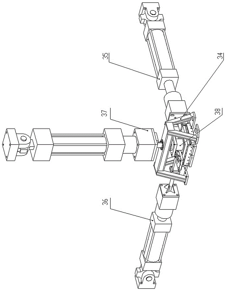
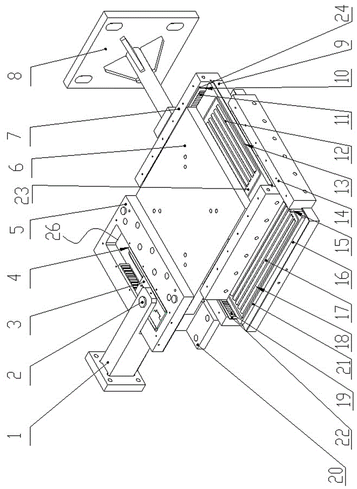
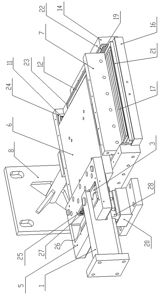
[0033] Combine below Figure 1 to Figure 6 The structure and working process of the present invention are further described.

[0034] A three-way mechanical test platform of the present invention comprises a three-layer structure consisting of an upper load-bearing plate 6, a middle load-bearing plate 9 and a lower force-bearing plate 16, the two sides of the lower force-bearing plate 16 along the X direction An X-direction rail 14 is fixedly arranged on the side, the middle bearing plate 9 is located between the X-guiding rails 14, and an X-direction roller row 18 is arranged between the middle bearing plate 9 and the lower bearing plate 16, An X lateral roller row 15 is arranged between the middle bearing plate 9 and the X guiding rail 14; the X directional roller row 18 is composed of an X directional roller column 17 and an X directional roller cage 21. The X-direction roller cage 21 is provided with X-direction roller positioning holes (not marked in the drawings) that mat...


PUM


Abstract

The invention discloses a three-directional mechanical test platform which is of a three-layer structure consisting of an upper bearing plate, a middle bearing plate and a lower bearing plate, wherein X-direction guide tracks are fixedly arranged on two sides of the lower bearing plate in the X-direction; X-direction roller rows are arranged between the middle bearing plate and the lower bearing plate; X-side roller rows are arranged between the middle bearing plate and the X-direction guide tracks; Y-direction guide tracks are fixedly arranged on two sides of the middle bearing plate in the Y-direction; Y-direction roller rows are arranged between the upper bearing plates and the middle bearing plates; Y-side roller rows are arranged between the upper bearing plate and the Y-direction guide tracks; an X loading head is fixedly connected with one side of the middle bearing plate in the X direction; a Y leading head is connected with one side of the upper bearing plate in the Y direction; a decoupling mechanism is arranged between the Y loading head and the upper bearing plate. The three-directional mechanical test platform is large in movement range, high in bearing property and high in experiment precision, three-direction independent loading can be achieved, and one-direction, two-direction and three-direction mechanical testing on an experiment object can be achieved.

Description

technical field [0001] The invention belongs to the technical field of test equipment, and in particular relates to a three-way mechanical test platform. Background technique [0002] Traditional mechanical test platforms are mostly one-way and two-way. When performing a one-way test, one end of the test object is usually placed on the platform, and the other end is connected to the loading mechanism. By loading different loads, the static or dynamic mechanics of the test object can be obtained. characteristic. In the two-way mechanical test, the test object is connected with a loading mechanism in two directions, and generally a simple hinge or roller is used to reduce the influence of movement in all directions. Although this method can guarantee the correctness of the test method to a certain extent, However, the accuracy of the test is low and the range of motion that can be realized is limited by the structure. [0003] For the three-dimensional mechanical test, becau...

Claims


Application Information

Patent Timeline
Patent Type & Authority Applications(China)
IPC IPC(8): G01N3/08
Inventor 王建强张俊峰王建亮焦建国田野王海洋辛伟李政
Owner ZHENGZHOU UNIV
Learn More