Supercharge Your Innovation With Domain-Expert AI Agents!

Device for adjusting detection antenna phase center according to plane wave radiation characteristic

A technology of radiation characteristics and adjustment devices, applied to antennas, electrical components, etc., can solve the problems of calibration error, heavy weight, displacement, etc. of the performance of the tight field quiet zone, so as to reduce the influence of the gravity of the detection antenna and improve the accuracy.

Active Publication Date: 2015-05-27
BEIJING INST OF RADIO METROLOGY & MEASUREMENT
View PDF6 Cites 2 Cited by
  • Summary
  • Abstract
  • Description
  • Claims
  • Application Information

AI Technical Summary

Problems solved by technology

[0005] Therefore, it is necessary to provide a phase center adjustment mechanism of the probe antenna, which can meet the requirements of the consistency of the receiving probe antenna and the position of the plane to be inspected. Because the structure size of the low-frequency probe antenna is large and the weight is heavy, when the low-frequency probe antenna is installed When it is on the phase center adjustment mechanism, it is easy to cause the vertical adjustment mechanism on the phase center adjustment mechanism to be displaced by the influence of gravity, which will bring errors to the performance calibration of the tight field quiet zone

Method used


Image

  • Device for adjusting detection antenna phase center according to plane wave radiation characteristic
  • Device for adjusting detection antenna phase center according to plane wave radiation characteristic
  • Device for adjusting detection antenna phase center according to plane wave radiation characteristic

Examples


Embodiment Construction

[0019] In order to illustrate the present invention more clearly, the present invention will be further described below in conjunction with preferred embodiments and accompanying drawings. Similar parts in the figures are denoted by the same reference numerals. Those skilled in the art should understand that the content specifically described below is illustrative rather than restrictive, and should not limit the protection scope of the present invention.

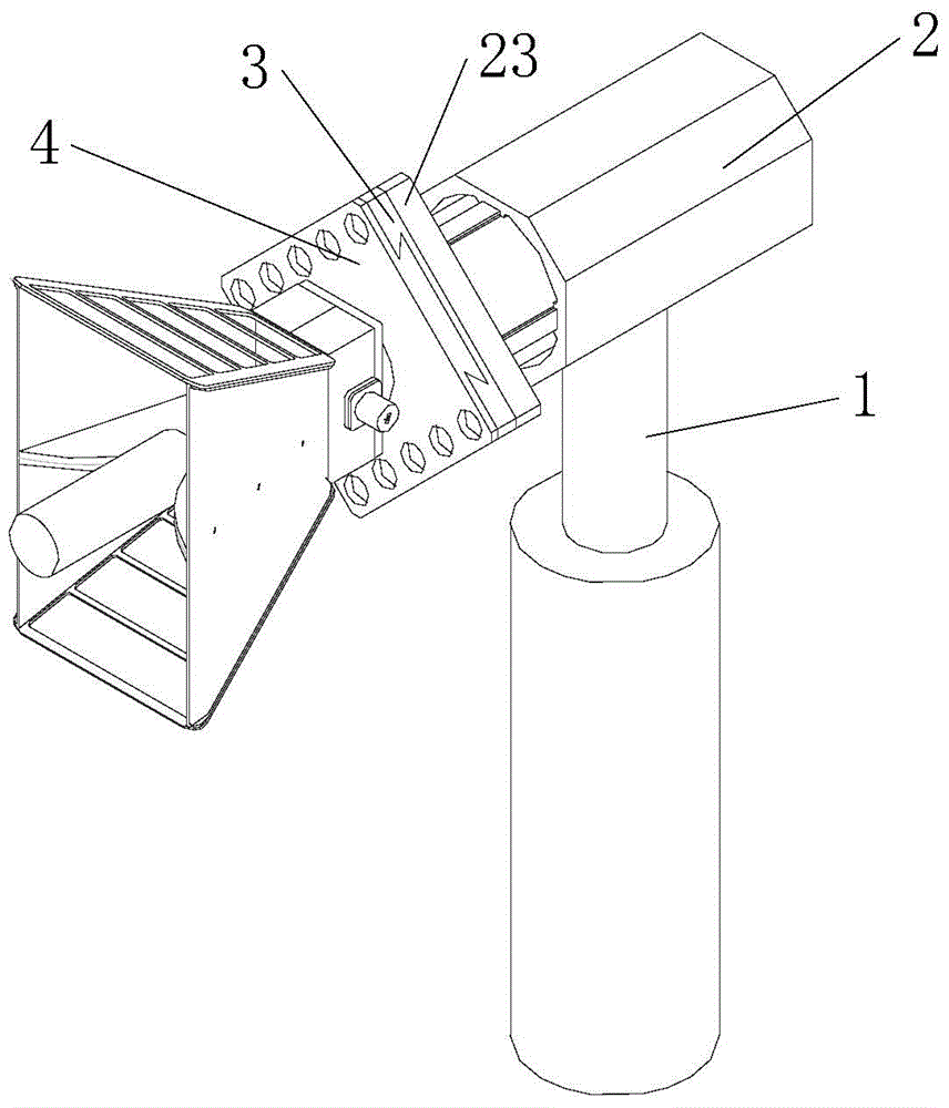
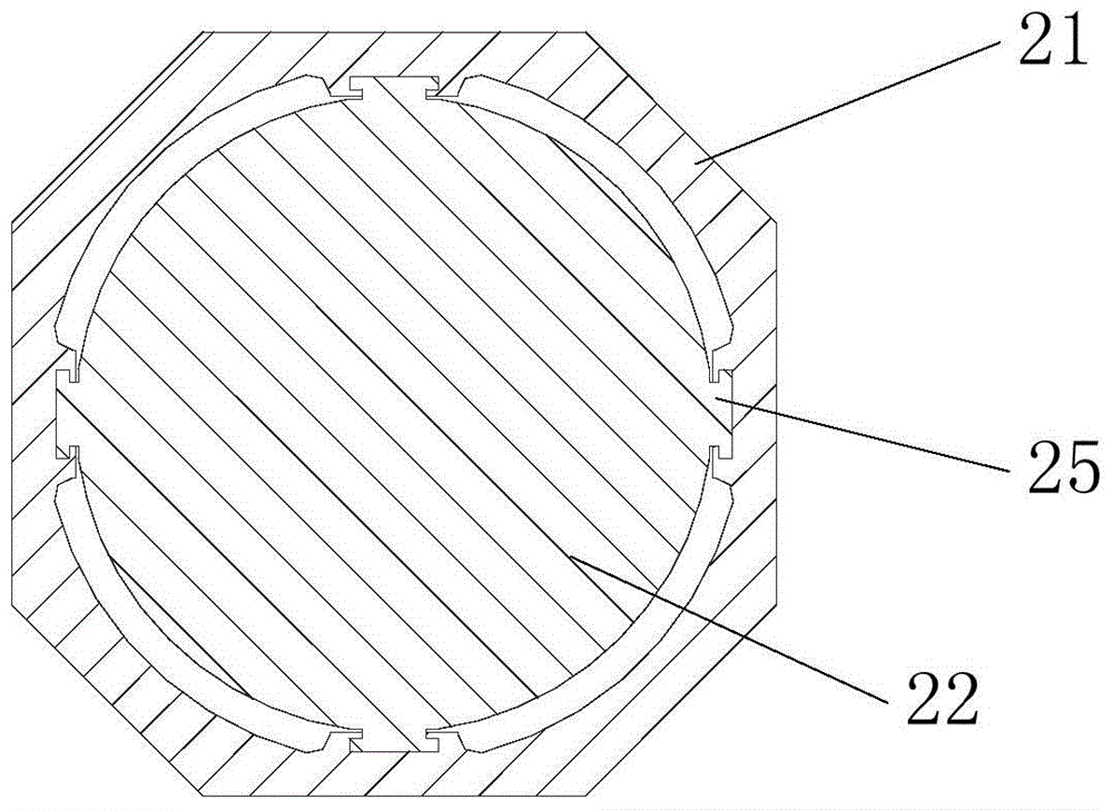
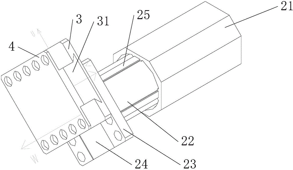
[0020] Such as Figure 1~3 As shown, a phase center adjustment device for a plane wave radiation characteristic detection antenna includes a bracket 1 , a cylindrical adjustment component 2 , a transverse rail seat 3 and a longitudinal rail seat 4 . The sleeve-type adjusting part 2 includes a hollow cylindrical outer sleeve 21 and an inner sleeve 22, the inner sleeve 22 is located inside the outer sleeve 21 and is slidably connected with the outer sleeve 21 by a linear ball screw, and the inner sleeve 22 The sleeve 22 is ...


PUM


Abstract

The invention discloses a device for adjusting the detection antenna phase center according to a plane wave radiation characteristic. The device comprises a support, a cylindrical adjusting part, a transverse guide rail seat and a vertical guide rail seat, wherein the cylindrical adjusting part comprises an inner sleeve and an outer sleeve; the outer sleeve is connected with the inner sleeve through a linear ball screw I, and horizontally fixed on the support; a base is arranged on an end surface of the inner sleeve; the transverse guide rail seat is connected with the base through a linear ball screw II; matched first dovetail grooves are formed in the contact surfaces of the transverse guide rail seat and the base; under the action of the linear ball screw II, the transverse guide rail seat slides along the first dovetail grooves; the included angle between the sliding direction of the transverse guide rail seat and the horizontal plane is 45 degrees; the vertical guide rail seat is connected with the transverse guide rail seat through a linear ball screw III; matched second dovetail grooves are formed in the contact surfaces of the vertical and transverse guide rail seats; the vertical guide rail seat slides along the second dovetail grooves; the included angle between the sliding direction of the vertical guide rail seat and the horizontal plane is 45 degrees; the sliding direction of the vertical guide rail seat is perpendicular to that of the transverse guide rail seat. As the gravity effect on the device is weak, the device is high in adjusting precision.

Description

technical field [0001] The invention relates to an antenna phase center adjustment mechanism, in particular to a plane wave radiation characteristic detection antenna phase center adjustment device. Background technique [0002] The compact field is a device that uses a precise reflector or microwave lens to convert the spherical wave emitted by the feed source into a plane wave within a short distance. The quasi-plane wave generated by it can fully meet the environmental requirements of the antenna, radome electromagnetic characteristics and target RCS test . [0003] There are many ways to calibrate the performance of the quiet zone in the tight field. The most common method in the world is the probe scanning method, that is, the standard probe antenna is used to directly test and evaluate the amplitude and phase of the plane wave field in the tight field test area. In the probe antenna scanning method , according to international practice and actual situation, usually on...

Claims


Application Information

Patent Timeline
IPC IPC(8): H01Q3/02
Inventor 黄建领马永光韩玉峰
Owner BEIJING INST OF RADIO METROLOGY & MEASUREMENT
Features
  • R&D
  • Intellectual Property
  • Life Sciences
  • Materials
  • Tech Scout
  • Unparalleled Data Quality
  • Higher Quality Content
  • 60% Fewer Hallucinations
Learn More