Distribution box base with fixed mount
A fixed frame and distribution box technology, applied in the direction of electrical components, substation/switch layout details, etc., can solve the problems of difficult disassembly between the distribution box and the base, low connection strength, cumbersome operation, etc., and achieve simple structure and easy operation , The effect of easy disassembly
- Summary
- Abstract
- Description
- Claims
- Application Information
AI Technical Summary
Problems solved by technology
Method used
Image

Examples
Embodiment Construction
[0011] The specific implementation manner of the present invention will be described below in conjunction with the accompanying drawings.
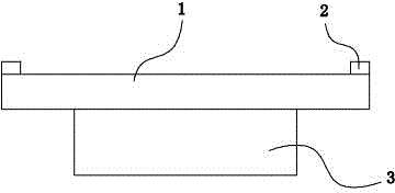
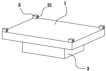
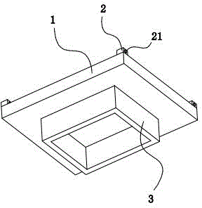
[0012] See Figure 1 to Figure 3 , the present invention comprises a bottom plate 1 of square structure, the four corners of the upper surface of the bottom plate 1 are respectively connected with stoppers 2, the stoppers 2 have threaded through holes 21, and the distribution box (not shown) is placed on the bottom plate The upper surface is located between the stoppers 2, and is locked and fastened through the threaded through hole 21 by means of screws; the middle part of the lower surface of the bottom plate 1 is connected to a square fixed frame surrounded by the fixed plate 3, and the square fixed frame is buried in the ground. , improve the stability of the connection between the base and the ground.
[0013] The above description is an explanation of the present invention, not a limitation of the invention. For the limited scope of...
PUM
 Abstract
Description
Claims
Application Information
 - Generate Ideas
- Intellectual Property
- Life Sciences
- Materials
- Tech Scout
- Unparalleled Data Quality
- Higher Quality Content
- 60% Fewer Hallucinations
Browse by: Latest US Patents, China's latest patents, Technical Efficacy Thesaurus, Application Domain, Technology Topic, Popular Technical Reports.
© 2025 PatSnap. All rights reserved.Legal|Privacy policy|Modern Slavery Act Transparency Statement|Sitemap|About US| Contact US: help@patsnap.com