
Mobile phone charger with cooling fan

A mobile phone charger and cooling fan technology, which is applied in current collectors, electric vehicles, electrical components, etc., can solve the problems of large power consumption and insufficient battery life, and achieve good cooling effects

Inactive Publication Date: 2015-05-27
XIAN SHUZHENG ELECTRONICS TECH
View PDF0 Cites 7 Cited by
  • Summary
  • Abstract
  • Description
  • Claims
  • Application Information

AI Technical Summary

Problems solved by technology

[0005] On the other hand, the current radiator is often just a radiator and has no other function, so it can only improve heat generation, but cannot solve the problem of high power consumption and insufficient battery life

Method used


Image

  • Mobile phone charger with cooling fan

Examples


Embodiment 1

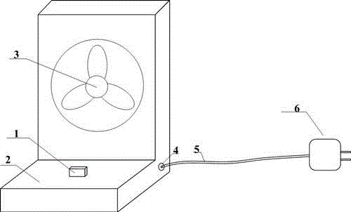
[0016] A mobile phone charger with a cooling fan, comprising a mobile phone charging interface 1, a charger base 2, a cooling fan 3, a power line interface 4, a power line 5, and a power adapter 6. The mobile phone charging interface 1 is embedded in the bottom of the charger base 2 . The mobile phone charging interface 1 is connected with the power line 5 . The cooling fan 3 is installed on the top of the charger base 2 . The cooling fan 3 is connected with the power line 5 . There is a power cord interface 4 on the side of the charger base 2 . One end of the power cord 5 is connected to the power cord interface 4 . The other end of the power cord 5 is connected with the power adapter 6 .

[0017] Because the heat dissipation fan 3 is inlaid on the front of the upper part of the charger base, it can play a cooling effect when rotating; and the current provided by the power adapter can charge the mobile phone at the same time. It has played a good effect on solving the sh...

Embodiment 2

[0019] A mobile phone charger with cooling fan according to claim 1, characterized in that: the charger base is "L" shaped, with a charging interface on the lower part, and a cooling fan installed on the upper part. In this way, mobile phones of various sizes can be better placed on the base. When the power supply is plugged in, the power adapter transmits the output DC power to the fan and the charging interface of the mobile phone through the wire and the power interface. When the mobile phone is plugged into the charging interface of the present invention, it can simultaneously charge and cool down. This has a good effect on improving the usage time and reducing the temperature of large-screen smartphones.

[0020] A mobile phone charger with cooling fan according to claim 1, characterized in that: the mobile phone charging interface adopts a USB interface, which can meet the charging requirements of most mobile phones on the market.

[0021] According to the theory of hea...


PUM


Abstract

The invention belongs to the technical field of mechanical design and consumer electronics, and particularly provides a mobile phone charger with a cooling fan. The mobile phone charger comprises a mobile phone charging interface, a charger base, a cooling fan, a power line interface, a power line, and a power adapter. The mobile phone charging interface is embedded into the lower part of the charger base, and is connected with the power line. The cooling fan is mounted on the upper part of the charger base, and is connected with the power line. The power line interface is arranged in a side of the charger base. One end of the power line is connected with the power line interface, and the other end of the power line is connected with the power adapter. The problem that the existing smart phone gives out a large amount of heat to cause high energy consumption and damage to the health of users is solved. The mobile phone charger of the invention adopts a low-power fan design scheme, so that the temperature of a mobile phone can be reduced greatly while energy is saved, and a good cooling effect is achieved. The experience of users in playing large games and watching films on a smart phone is effectively enhanced.

Description

technical field [0001] The invention belongs to the fields of mechanical design and consumer electronics, and in particular relates to a mobile phone charger with a cooling fan. Background technique [0002] The current smartphones generally suffer from excessive energy consumption and excessive heat generation, resulting in a sharp decline in user experience; thus, heat dissipation has become an important research direction. [0003] Most of the current heat sinks only use the natural heat conduction of metals, that is, metal materials are used on heat dissipation devices such as support frames of mobile phones, so that heat can be quickly taken away by metals. The advantage of doing this is that the cost is low and the reliability is high. The disadvantage is that the natural heat conduction of metal still cannot play a good role when the mobile phone heats up a lot. [0004] The theory of heat conduction tells us that air can conduct heat, and the faster the air flows, ...

Claims


Application Information

Patent Timeline
Patent Type & Authority Applications(China)
IPC IPC(8): H02J7/00
CPCH02J7/0042
Inventor 潘鑫
Owner XIAN SHUZHENG ELECTRONICS TECH
Learn More