
Power system structure

A power system and power module technology, applied in the mechanical field, can solve the problems of small space and large volume of high-power converters, and achieve the effect of high-power structure, high power density and compact structure

Pending Publication Date: 2015-05-27
ZHEJIANG HAIDE NEW ENERGY
View PDF6 Cites 4 Cited by
  • Summary
  • Abstract
  • Description
  • Claims
  • Application Information

AI Technical Summary

Problems solved by technology

[0003] The present invention provides a power system structure, the purpose of which is to solve the technical problems of excessive volume and small space of the existing high-power converters

Method used


Image

  • Power system structure
  • Power system structure
  • Power system structure

Examples


Embodiment Construction

[0018] The following are specific embodiments of the present invention and in conjunction with the accompanying drawings, further describe the technical solution of the present invention, but the present invention is not limited to these embodiments.

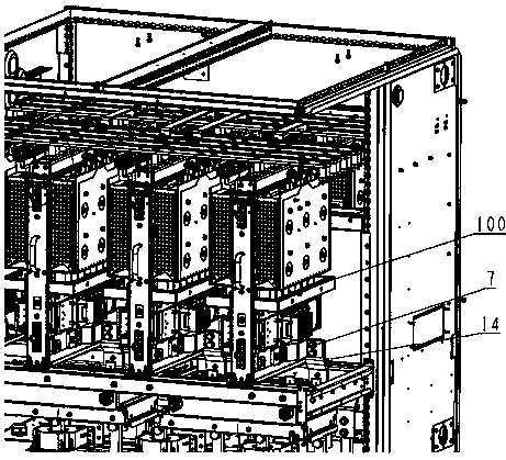
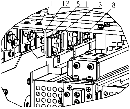
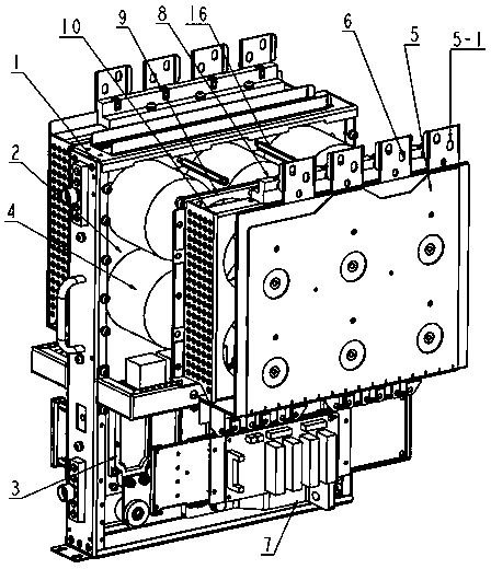
[0019] Such as figure 1 and figure 2 , a power system structure, including a power module and a structure connected to the system, wherein the power module 100 includes a module fixing bracket 1, a water cooling plate 2, an IGBT 3, a bus capacitor 4, a DC positive busbar 5, and a DC negative busbar row 6, AC copper bar 7, fixed block 8 of DC busbar, busbar capacitor fixing plate 9, busbar capacitor clamping plate 10 and capacitor clamping rod 16, such as image 3 The structure for system connection with the power module 100 includes the main bus bar copper bar 11, the transfer copper bar 12, the transfer copper bar nut plate 13, and the system AC copper bar 14; the DC positive bus bar 5 above the power module 100, the DC The ...


PUM


Abstract

The invention relates to a power system structure which comprises a power module and a structure connected with a system, wherein a direct-current positive busbar is arranged above the power module; a direct-current negative busbar and a main bus copper bar are connected through a transfer copper bar; the structure connected with the system comprises a transfer copper bar nut plate and a compression module direct-current busbar leading-out terminal of the transfer copper bar; an alternating-current copper bar on the rear lower side of the power module is directly connected with an alternating-current copper bar of the system; a bus capacitor passes through a bus capacitor fixing plate, and a bus capacitor clamping plate and a capacitor clamping pull rod are fixed on a module fixing bracket and a water cooling plate; two terminals of the direct-current positive busbar and two terminals of the direct-current negative busbar are upward, are led out and are respectively connected with the main bus copper bar. With the adoption of the system structure and the power module structure provided by the invention, high power density, compact structure and a good water cooling heat dissipation effect of the bus capacitor and an IGBT (Insulated Gate Bipolar Transistor) can be realized; a direct-current copper bar and the alternating-current copper bar of the power module are respectively led out up and down; through a transfer structure, mounting and connection are reliable and convenient, and the characteristics of high power and compact structure are realized.

Description

technical field [0001] The invention relates to a power system structure applied to a high-power converter, including a power module and a system connection structure, and belongs to the mechanical field. Background technique [0002] The invention relates to a structural scheme of a power system. For current high-power converters, the increase in power density leads to larger volume, and the smaller space of the entire system leads to increased difficulty in system connection; the system current is getting larger and larger, requiring must There is a reliable system connection. This requires the power system structure to be very compact, and does not affect the performance of installation and maintenance. Contents of the invention [0003] The invention provides a power system structure, which aims to solve the technical problems of the existing high-power converters with too large volume and small space. [0004] The technical solution of the present invention: a power...

Claims


Application Information

Patent Timeline
Patent Type & Authority Applications(China)
IPC IPC(8): H02M1/00H02M7/00H05K7/20
Inventor 吴永祥郭可豪
Owner ZHEJIANG HAIDE NEW ENERGY
Learn More