An Optimal Optical Time Domain Reflectometer

An optical time domain reflectometer and laser technology, which is applied to electrical components, electromagnetic wave transmission systems, transmission systems, etc., can solve problems such as reducing the dynamic range, and achieve the effects of adjustable pulse width, strong practical value, and adjustable pulse frequency.

Active Publication Date: 2019-04-05
GLOBAL ENERGY INTERCONNECTION RES INST CO LTD +1
View PDF3 Cites 0 Cited by
  • Summary
  • Abstract
  • Description
  • Claims
  • Application Information

AI Technical Summary

Problems solved by technology

Similarly, if a fixed narrow pulse is used as the detection signal, the resolution will be significantly improved, but it will also cause a decrease in the dynamic range.

Method used


Image

  • An Optimal Optical Time Domain Reflectometer
  • An Optimal Optical Time Domain Reflectometer
  • An Optimal Optical Time Domain Reflectometer

Examples


Embodiment 1

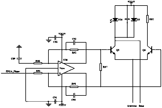
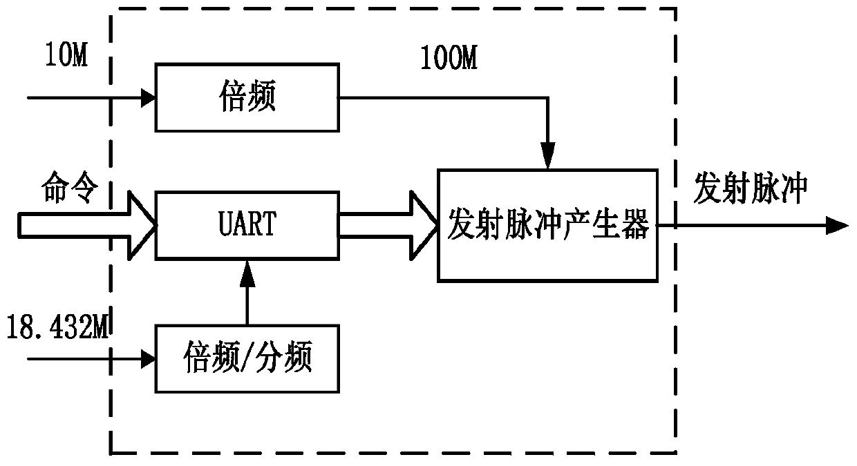
[0026] The invention of this example provides an optimized optical time domain reflectometer, including a pulse generator and a laser connected to the pulse generator; the pulse generator is a pulse generator that adopts FPGA to generate frequency and adjustable pulse width; the The laser is triggered by a current to emit light pulses of a certain power, so the pulses of different pulse widths and frequencies generated by the FPGA control the laser pulse drive circuit to generate current pulses with a certain width and frequency to drive the laser.

[0027] Such as figure 2 As shown, according to the main controller through the UART interface and FPGA communication to control pulse generation or not. Such as image 3 As shown, the pulse waveform generated by the pulse generator is shown.

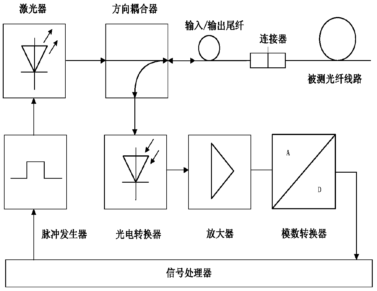
[0028] Such as figure 1 As shown, the laser, the directional coupler, the pigtail connection, the connector and the optical fiber line under test are connected sequentially; the pigtail,...


PUM


Abstract

The invention relates to an optimized optical time domain reflectometer, comprising a pulse generator and a laser in connection with the pulse generator. The pulse generator is a pulse generator which uses FPGA to generate frequencies and adjustable pulse widths. The pulses generated by the FPGA with different pulse widths and different frequencies drive the laser by controlling the laser pulse drive circuit to generate current pulses with widths and frequencies. The technical schemes of the invention greatly increase the dynamic detection scope and the resolution of an optical time domain reflectometer.

Description

Technical field: [0001] The invention relates to the technical field of analysis and measurement control, and more specifically relates to an optimized optical time domain reflectometer. Background technique: [0002] With the increasingly widespread application of optical fiber communication technology in various fields, the testing of optical fiber has become an indispensable and important link in the development, construction and maintenance of optical fiber application systems. As a special optical fiber testing instrument, the optical time domain reflectometer can measure the entire length of the optical fiber, analyze the attenuation of the entire optical fiber link and provide details of the attenuation related to the length, so as to accurately locate events such as joints and breakpoints in the optical fiber, It is the most frequently used field instrument in the fiber optic system. [0003] Optical time domain reflectometer technology is complex and difficult to d...

Claims


Application Information

Patent Timeline
Patent Type & Authority Patents(China)
IPC IPC(8): H04B10/071
CPCH04B10/071
Inventor 侯功彭林韩海韵于海鲍兴川王刚王鹤徐敏侯战胜朱亮
Owner GLOBAL ENERGY INTERCONNECTION RES INST CO LTD
Why Eureka
Try Eureka