Braking apparatus for electric power tool

A technology of electric tools and braking devices, which is applied in the direction of deceleration devices, stop devices, and portable mobile devices of DC motors, which can solve problems such as large reaction force, damage to the user's sense of use, and poor electrical equipment, so as to prevent Effect of high temperature and prevention of regenerative current flow

Active Publication Date: 2015-05-27
MAKITA CORP
View PDF5 Cites 19 Cited by
  • Summary
  • Abstract
  • Description
  • Claims
  • Application Information

AI Technical Summary

Problems solved by technology

[0006] However, in the above-mentioned conventional short-circuit braking, the braking current flows through all phases of the three-phase brushless motor to generate a braking force, so the braking force may be too large, and the force exerted by the braking force on the electrical equipment may increase. Bad electrical equipment
[0007] For example, in an electric ...

Method used


Image

  • Braking apparatus for electric power tool
  • Braking apparatus for electric power tool
  • Braking apparatus for electric power tool

Examples


Embodiment Construction

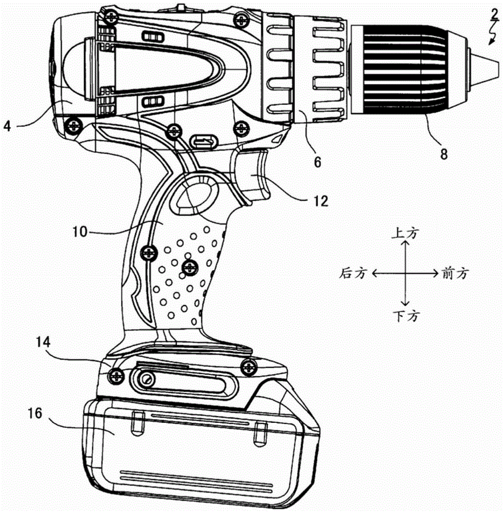
[0071] The following is attached Figure 1 Embodiments of the present invention will be described first.

[0072] like figure 1 As shown, the electric tool 2 of the present embodiment is a so-called electric drill, and includes a motor housing 4, a gear (Gear) housing 6 located in front of the motor housing 4, a drill chuck 8 located in front of the gear housing 6, and a drill chuck 8 located in front of the gear housing 6. The handle 10 below the motor housing 4.

[0073] The motor housing 4 accommodates a motor 20 that generates a driving force that drives the drill chuck 8 (refer to figure 2 ). Furthermore, the motor 20 is a three-phase brushless motor. The gear case 6 accommodates a gear mechanism (not shown) that transmits the driving force of the motor 20 to the drill chuck 8 .

[0074] The drill chuck 8 includes an attachment mechanism (not shown) for detachably attaching a tool bit (not shown) to the front end portion of the drill chuck 8 .

[0075] The handle 1...


PUM


Abstract

One aspect of an embodiment of the present disclosure is a braking apparatus for an electric power tool that includes a switching circuit with six switching elements and a brake control unit. The brake control unit switches any one selected switching element of three switching elements forming one selected switch group of a high-side switch group and a low-side switch group to an off state from an on state at a timing at which braking current flows through a diode connected in parallel to the selected switching element upon turn-off of the selected switching element.

Description

technical field [0001] The present invention relates to a brake device for an electric tool that generates a braking force by short-circuiting terminals of the motor in an electric tool including a three-phase brushless motor. Background technique [0002] Conventionally, in electric tools using a three-phase brushless motor as a driving source, when the rotation of the three-phase brushless motor is reduced or stopped, a so-called short-circuit that short-circuits between terminals of the three-phase brushless motor to generate a braking force is used. braking (for example, refer to Patent Document 1). [0003] In this short-circuit braking, for example, three switching elements (so-called low-side switches) provided in the conduction path between each terminal of the three-phase brushless motor and the negative pole of the DC power supply are turned on, and the Three switching elements (so-called high-side switches) of the energization path between each terminal of the th...

Claims


Application Information

Patent Timeline
IPC IPC(8): H02P6/24
CPCH02P3/12B25F5/00
Inventor 石川刚史加藤慈
Owner MAKITA CORP
Why Eureka
Try Eureka