Plant propagation device and culturing panel

A technology for cultivating trays and plants, which is applied in the field of plant transplanting devices and cultivating trays, which can solve the problems of plant strain damage, residue, and inability to extend to the hole, and achieve the effect of improving production efficiency and efficiency

Inactive Publication Date: 2015-05-27
TSUBAKIMOTO CHAIN CO
View PDF6 Cites 0 Cited by
  • Summary
  • Abstract
  • Description
  • Claims
  • Application Information

AI Technical Summary

Problems solved by technology

[0013] However, according to the known transplanting device with the suction mechanism of Patent Document 1, the following problem can occur: when a part or all of the root of the plant is not inserted into the hole and stays on the upper periphery of the hole, it is not fully absorbed. attraction, so that it cannot extend below the hole portion resulting in residual
[0014] In addition, the root inserted into the hole may also have the following problem: when the amount or expansion is large and it is pressed against the inner surface of the hole, part or all of the root may be damaged due to the gap between the root and the inner surface of the hole. Stuck against extrusion and unable to extend below the hole
[0015] In order to solve these problems, although it can be considered to increase the attractive force, since most of the roots of the plants are loosely intertwined and interconnected, the air intake is only increased but the force of attracting the roots is not fully increased. On the contrary , it will become a strong attraction to the plant itself (or the cultivation bucket for maintaining the plant) to the hole, so as to cause damage to the plant

Method used


Image

  • Plant propagation device and culturing panel
  • Plant propagation device and culturing panel
  • Plant propagation device and culturing panel

Examples


Embodiment 1

[0057] Regarding the plant strain transplanting device according to the first embodiment of the present invention, based on figure 2 Be explained.

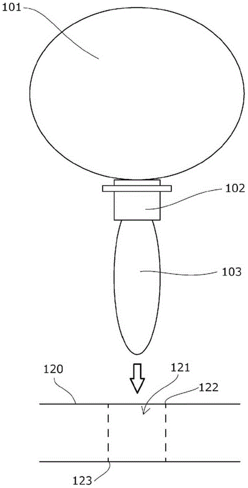
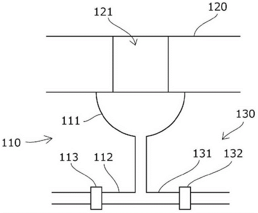
[0058] The plant transplanting device according to the present embodiment includes: a suction mechanism 110 for sucking the roots of the plants and passing them through the holding holes 121 of the cultivation tray 120 as a hole; and a water supply mechanism 130 for supplying water to the roots of the plants. .

[0059] The suction mechanism 110 has: a suction cylinder 111 that can be closely attached to the lower side of the holding hole 121, and a suction pipe 112 for making the inside of the suction cylinder 111 negative. A valve 113 for opening and closing suction is arranged on the suction pipe 112.

[0060] The water supply mechanism 130 has a water supply pipe 131 for supplying water from the inside of the suction cylinder 111 toward the hole, and a valve 132 for turning on and off the water supply is arranged on the wate...

Embodiment 2

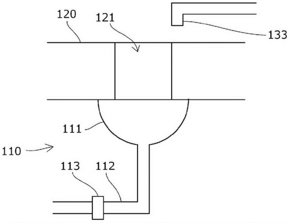
[0065] Regarding the plant strain transplanting device according to the second embodiment of the present invention, based on image 3 Be explained.

[0066] The plant strain transplanting device according to this embodiment is the same as the above-mentioned first embodiment except for the water supply mechanism 130 .

[0067] The water supply mechanism 130 has a water discharge nozzle 133 that supplies water from above the holding hole 121 .

[0068] The negative pressure generation source of the suction pipe 112 and the water supply source of the water discharge nozzle 133, which are not shown in the figure, may have any configuration, and the supply of water from the water discharge nozzle 133 may be opened and closed by a valve or the like as necessary, or may be It is constantly supplied from the water supply source.

[0069] Moreover, the water supply mechanism 130 may further have the water supply piping 131 which supplies water from the suction cylinder 111 similar t...

Embodiment 3

[0072] Regarding the plant strain transplanting device according to the third embodiment of the present invention, based on Figure 4 Be explained.

[0073] The plant strain transplanting device according to the present embodiment is provided with suction cylinders 111 corresponding to one row of holding holes 121 of a cultivation tray 120 provided with a plurality of holding holes 121 .

[0074] In addition, the water supply mechanism 130 ( Figure 4 (not shown in the figure) are also provided to correspond to one row of holding holes 121 .

[0075] The configuration of the water supply mechanism 130 may be any one of the above-mentioned first embodiment and the second embodiment, or both may be included, and other configurations may be used as long as water can be supplied to the holding holes 121 in one row. Way.


PUM


Abstract

There is provided a plant transplantation device capable of reliably sucking a root of a plant into a hole portion, reliably causing the root of the plant to extend downward from the hole portion without remaining in the hole portion, and improving production efficiency without requiring monitoring or manual operations with a simple configuration. The plant transplantation device includes a suctioning means 110 for sucking a root 103 of a plant 101 and causing the root 103 of the plant 101 to pass through a hole portion 121, the suctioning means 110 has a suctioning tube 111 which can be hermetically attached to a lower portion of the hole portion 121 and a suction pipe 112 which causes a negative pressure in the suctioning tube 111, and a water supplying means 130 for supplying water to the root 103 of the plant 101 is provided in the vicinity of the hole portion 121.

Description

technical field [0001] The present invention relates to a plant transplanting device and a cultivation tray having a suction mechanism for attracting the roots of plants and passing them through holes, for example, to the following plant transplanting devices and cultivation trays: In tillage cultivation equipment, plant strains are transplanted into holding holes of different cultivation trays according to the growth status. Background technique [0002] As everyone knows, in the past, there is such a hydroponic cultivation equipment: in places such as plant factories, plant strains are kept on holding parts, for example, kept on a cultivation tray with a plurality of holding holes, and the holding holes extending to the cultivation tray The roots of the lower plant are immersed in the cultivation solution or the like, or the cultivation solution or the like is sprayed toward the roots. [0003] According to these hydroponic cultivation equipment, for example, in the case ...

Claims


Application Information

Patent Timeline
Patent Type & Authority Applications(China)
IPC IPC(8): A01G31/02A01G9/08A01G31/00
CPCA01G9/08A01G31/02A01G9/0299A01C11/00
Inventor 平井达也河野浩二冈崎由大原均
Owner TSUBAKIMOTO CHAIN CO
Why Eureka
Try Eureka