
Breeding loop

A technology of loop and aquaculture ponds, applied in fish farming, application, climate change adaptation, etc., can solve the problems of reduced land utilization, low efficiency, large floor space, etc., to reduce infrastructure costs and improve work efficiency. Effect

Active Publication Date: 2015-06-03
HAINAN WENCHANG LIYANG SHRIMP BREEDING
View PDF6 Cites 3 Cited by
  • Summary
  • Abstract
  • Description
  • Claims
  • Application Information

AI Technical Summary

Problems solved by technology

[0003] At present, electronic markers, fluorescent markers, molecular markers and genetic markers can be used for aquatic animal markers, but no matter what kind of markers are used, they have disadvantages such as high cost (especially electronic markers), difficult operation, affecting survival rate, and limited duration. However, if the test is carried out in the same environment without marking in Datang, many cages are needed, and there are also problems such as the cages are not easy to clean and easy to block.
There is also a separate construction of the ring road, but it also has the disadvantages of large floor area and low land utilization rate, and the function of the ring road for isolation and testing is not considered, so marking or cage screening cannot be avoided, resulting in increased breeding costs and labor intensity. Disadvantages such as becoming larger and reducing land utilization
[0004] In the prior art, when marking fish research or aquatic organism breeding, the use of electronic markers, fluorescent markers, molecular markers, and gene markers is costly, difficult to operate, and affects the survival rate, while net bags or other artificial methods are usually used Capturing aquatic organisms in net cages is inconvenient and inefficient. There is an urgent need for a low-cost, easy-to-operate marking device that can be automatically controlled without affecting the survival rate.

Method used


Image

  • Breeding loop
  • Breeding loop
  • Breeding loop

Examples


Embodiment Construction

[0045] In order to make the object, technical solution and advantages of the present invention clearer, the present invention will be further described in detail below in combination with specific embodiments and with reference to the accompanying drawings. It should be understood that these descriptions are exemplary only, and are not intended to limit the scope of the present invention. Also, in the following description, descriptions of well-known structures and techniques are omitted to avoid unnecessarily obscuring the concept of the present invention.

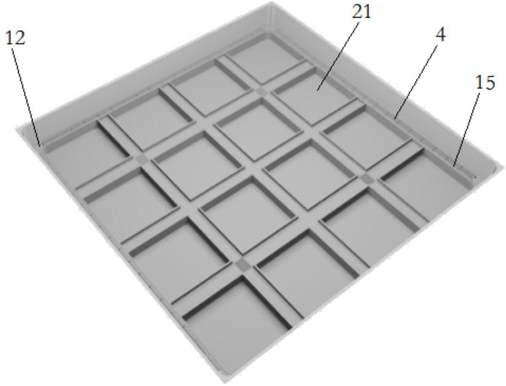
[0046] According to an embodiment of the present invention, such as figure 1 Shown is a perspective top view of a circuit according to the invention. The breeding loop of the present invention comprises a loop 4 and is divided into several breeding ponds 21 surrounded by the loop 4 .

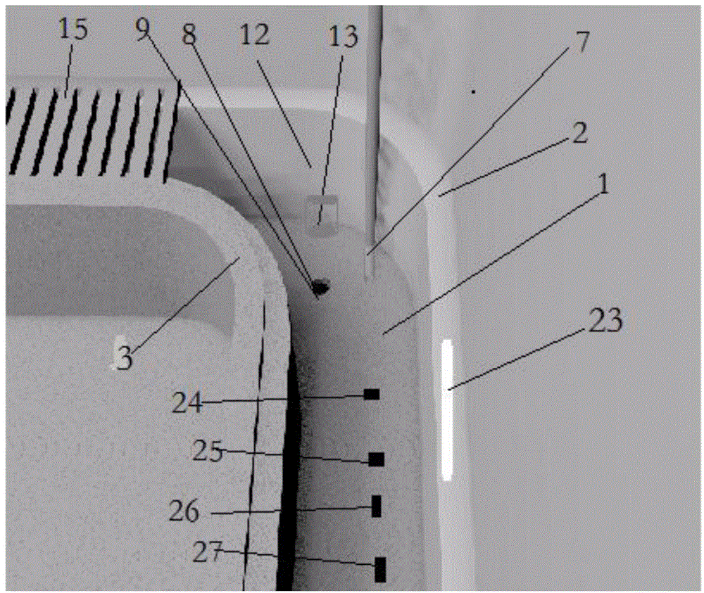
[0047] like figure 2 Shown is a perspective view of a corner portion of a ring track according to the invention. see figure 2 The r...


PUM


Abstract

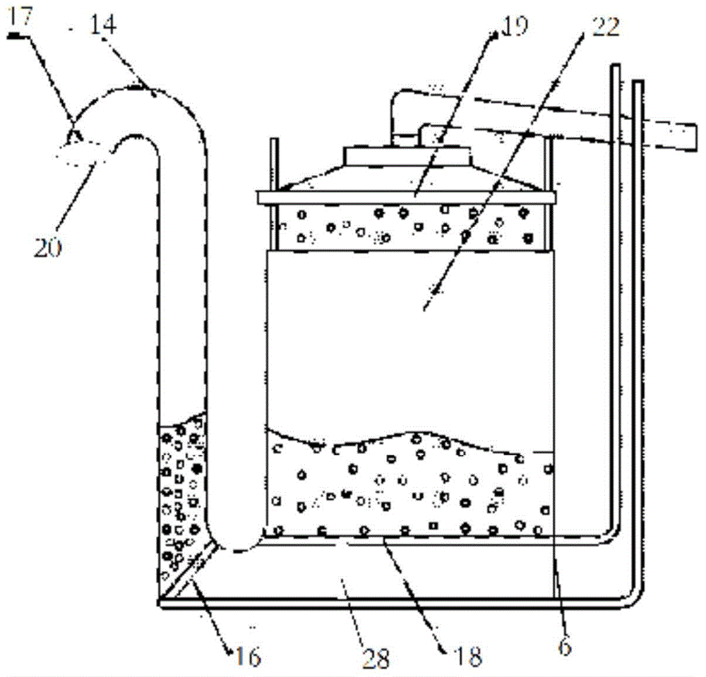
The invention relates to a breeding loop which comprises a loop (4) and a plurality of culture ponds (21), wherein the plurality of culture ponds (21) are enclosed by the loop (4), an outer wall (2) of the loop is a waterproof treated workshop wall, a control unit (23) which is arranged on the outer wall (2) of the loop is used for controlling a flushing solenoid valve (5) to regulate water inflow, controlling an air pressure source (6) to regulate air inflow and controlling a valve (12) to open or close, so that aquatic organisms enter the predetermined culture ponds (21), the loop (4) is provided with a temperature sensor (24), a heating component (25), a PH sensor (26) and a PH regulating part (27), and data of the temperature sensor (24) and the PH sensor (26) are received by the electric control unit (23), so as to regulate the heating component (25) and the PH regulating part (27), so that the loop (4) is kept at constant temperature, and a PH value is from 7 to 7.9. The loop (4) has the advantages of low cost, simplicity and convenience in operation, capability of automatic control and no influence on the survival rate.

Description

technical field [0001] The invention relates to the technical field of selection and breeding of aquatic organisms, in particular to a controllable breeding loop built on walls and capable of circulating water in the loop. Background technique [0002] With the continuous development of modern science and technology and the need for further development and utilization of pelagic fish resources, the research on the various response behaviors of fish is more in-depth, so as to recognize the behavioral response characteristics of various fish and provide information in fishing operations. be utilized in. In fishing operations, fish have different responses to fishing nets. Making full use of these responses can promote the improvement of fishing techniques. In order to study the different responses of various fish to net gear, modern fish behavior research needs Experiments on fish response behavior to nets are carried out indoors to promote the development of fishing techniqu...

Claims


Application Information

Patent Timeline
IPC IPC(8): A01K61/00A01K63/00A01K63/04
CPCY02A40/81A01K63/003A01K63/04A01K63/042A01K63/065
Inventor 卢国兴周湖明王惠儒张文文姜玉声姚福向
Owner HAINAN WENCHANG LIYANG SHRIMP BREEDING
Learn More