Rolling mill
A rolling mill and roll technology, applied in the field of steel rolling equipment, can solve problems such as dismantling, complicated reassembly, difficult positioning and locking operations, and no connection relationship
- Summary
- Abstract
- Description
- Claims
- Application Information
AI Technical Summary
Problems solved by technology
Method used
Image

Examples
Embodiment Construction
[0016] For the convenience of explanation and understanding, some basic orientation and position concepts are explained and defined first.
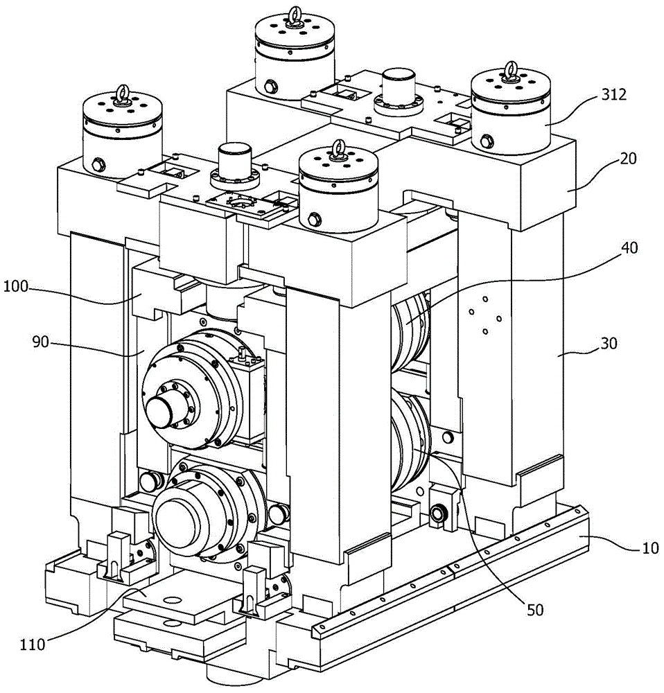
[0017] The power side or end of the rolling mill or roll refers to the side where the shaft end of the roll is connected to the power shaft, and the opposite side or end is the operating side or end; the incoming or incoming side of the roll refers to the side where the material to be rolled begins to enter the roll The rolling side, the discharge side of the roll refers to the side where the material to be rolled leaves the roll after being rolled; the up and down directions refer to the state where the roll is placed horizontally, and the following description only takes this state as an example. . The rolling mill can be placed in a vertical roll manner to implement rolling.
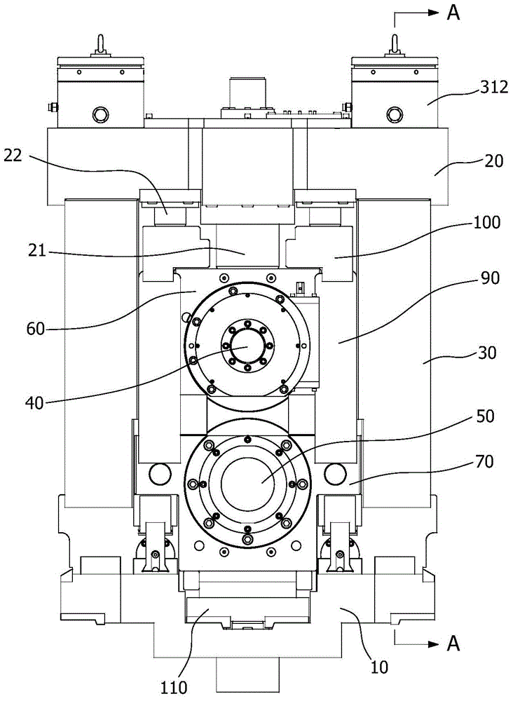
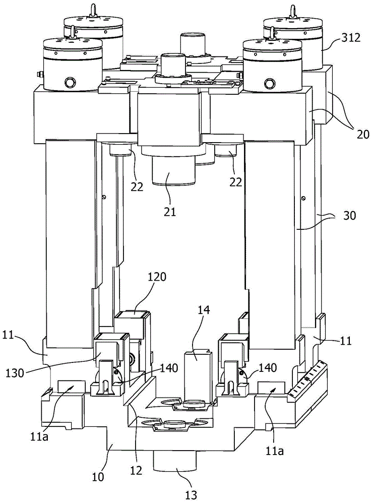
[0018] In conjunction with the accompanying drawings, the rolling mill includes a rolling mill base 10, an upper beam 20, and a frame formed by a column 30 stan...
PUM
 Abstract
Description
Claims
Application Information
 - R&D
- Intellectual Property
- Life Sciences
- Materials
- Tech Scout
- Unparalleled Data Quality
- Higher Quality Content
- 60% Fewer Hallucinations
Browse by: Latest US Patents, China's latest patents, Technical Efficacy Thesaurus, Application Domain, Technology Topic, Popular Technical Reports.
© 2025 PatSnap. All rights reserved.Legal|Privacy policy|Modern Slavery Act Transparency Statement|Sitemap|About US| Contact US: help@patsnap.com