Aircraft electric braking system

一种飞行器、电动制动的技术,应用在制动控制系统、飞机制动安排、制动器等方向,能够解决丧失、制动控制丧失等问题

Active Publication Date: 2015-06-03
AIRBUS OPERATIONS GMBH +1
View PDF6 Cites 15 Cited by
  • Summary
  • Abstract
  • Description
  • Claims
  • Application Information

AI Technical Summary

Problems solved by technology

Thus there is the potential for several EMACs to fail simultaneously resulting in partial or total loss of brake control, which is undesirable

Method used


Image

  • Aircraft electric braking system
  • Aircraft electric braking system
  • Aircraft electric braking system

Examples


Embodiment Construction

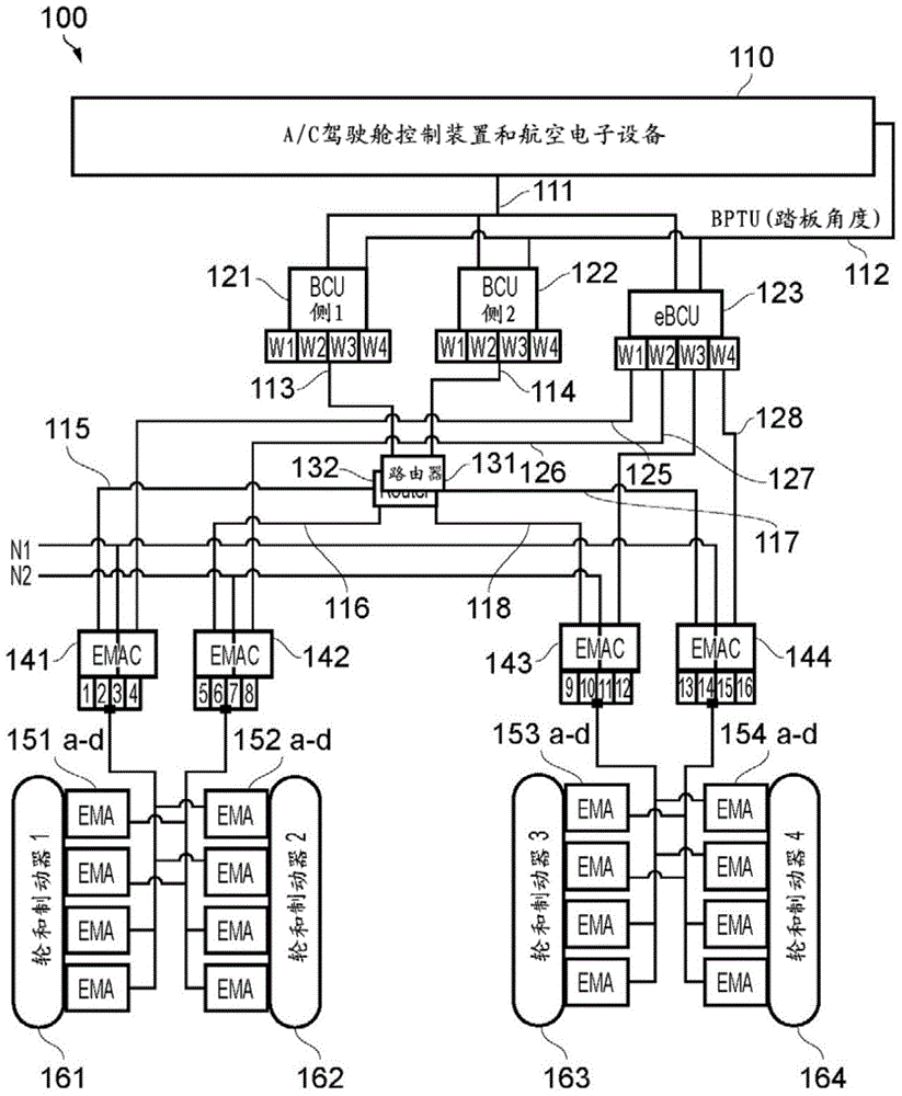
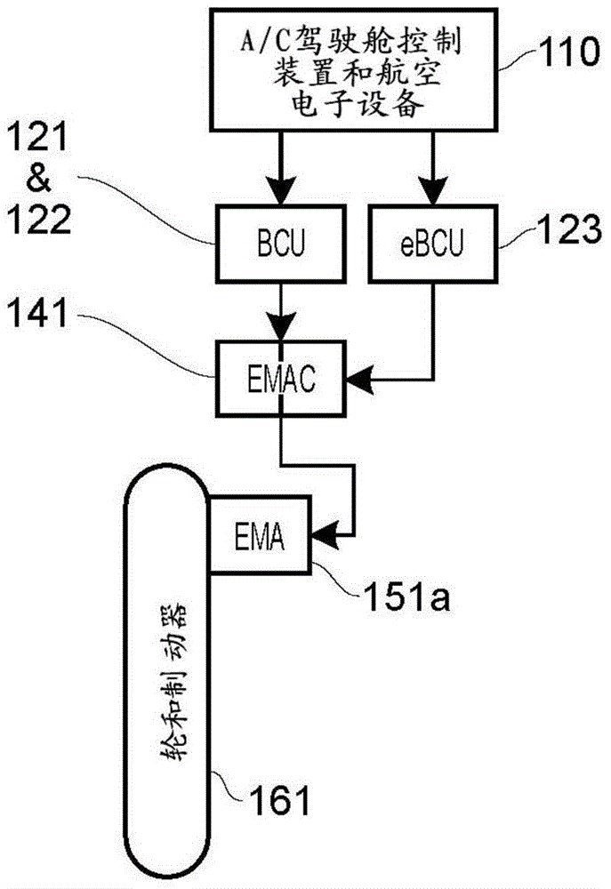
[0058] exist figure 1 The electric aircraft braking system 100 of the illustrated first embodiment is configured for use with an aircraft having two braked main landing gear, one of which is on either side of the aircraft centerline. It will be understood, however, that the invention described herein relates to any aircraft configuration having braked wheels, including aircraft having more than two main landing gear and / or braked nose landing gear.

[0059] The braking system 100 features centralized avionics. The braking system includes dual redundant braking control units (BCUs) 121, 122, which are assigned to specific sides, eg aircraft avionics grid side or power grid side (side 1, side 2, etc.). The BCUs 121 , 122 receive inputs from aircraft cockpit controls and avionics 110 via one or more data buses 111 and analog and / or discrete signals 112 (eg, from a brake pedal transmitter unit (BPTU) indicating braking pedal angle). Note that not all signal paths are shown in t...


PUM


Abstract

An electrically actuated braking system for an aircraft, comprising: an electro-mechanical brake actuator (EMAbrake) proximate a wheel of the aircraft, the EMAbrake including a motor; an electro-mechanical actuator controller (EMAC) including a first motor controller for generating a first drive signal for the EMAbrake, and a second motor controller for generating a second drive signal for the EMAbrake, wherein the first motor controller and the second motor controller are dissimilar so as to provide protection against common mode failure of the first and second motor controllers.

Description

technical field [0001] The present invention relates to an electric braking system for an aircraft. Background technique [0002] Electrical systems are gradually replacing hydraulic systems on many commercial and military aircraft. Current "brake-by-wire" aircraft systems may have an overall centralized architecture where pilot inputs are interpreted and command and monitoring signals communicated via a data bus as analog / discrete signals to a brake control unit (BCU). An exemplary centralized architecture is described in US 2008 / 0030069 A1. [0003] The BCU interprets commands from aircraft cockpit controls and avionics, and calculates braking force commands for each actuated landing gear wheel of the aircraft. This can include quick cycle skid control. [0004] Each brake wheel will have at least one electromechanical actuator (EMA) for providing a clamping force to the brakes for that wheel, which brake wheel converts the clamping force into a braking torque. An elec...

Claims


Application Information

Patent Timeline
Patent Type & Authority Applications(China)
IPC IPC(8): B60T13/74B60T8/17B60T8/32
CPCB60T8/1703B60T8/885B60T2270/402B60T13/741B64C25/44B64C25/46F16D2121/24B60T8/325B60T2270/404F16D65/14
Inventor 乔治·约尔扎尼季斯约翰·里斯
Owner AIRBUS OPERATIONS GMBH
Why Eureka
Try Eureka