Locking clamping track instrument

A rail clamp and locking technology, which is applied in the direction of travel mechanism, load hanging element, transportation and packaging, etc., can solve the problems of personal casualties of ground workers, easy slippage and deformation of the rail clamp, and overturning of the rail clamp. , to achieve the effect of increasing the contact area, simple and convenient installation and disassembly, and avoiding slippage and deformation

Active Publication Date: 2015-06-03
宝钢日铁汽车板有限公司
View PDF5 Cites 7 Cited by
  • Summary
  • Abstract
  • Description
  • Claims
  • Application Information

AI Technical Summary

Problems solved by technology

However, if figure 2 As shown, after the rail clip 10 is directly installed on the track 4, it can move and fall off on the rail 4 because there is no locking function. Especially in the track maintenance process, the maintenance personnel are easy to knock over the rail clip and In addition, when the rail clamp prevents the bridge crane from moving, its wheel 5 is stuck on the flat steel plate 3. The contact area between the flat steel plate 3 of the rail clamp and the wheel body on the arc surface is small, and the rail clamp 10 is easy to slip and deformation
In addition, since the rails of the bridge crane are all at high altitude, the rail clamps falling from the rails are likely to cause personal injury and death of ground workers

Method used


Image

  • Locking clamping track instrument
  • Locking clamping track instrument
  • Locking clamping track instrument

Examples


Embodiment Construction

[0044]The following will further explain and describe the locking rail device of the present invention with reference to the accompanying drawings and specific embodiments, but the explanation and explanation do not constitute an improper limitation to the technical solution of the present invention.

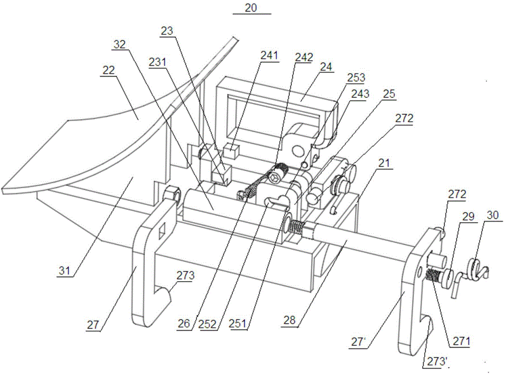
[0045] image 3 The assembly structure of the locking rail device according to the present invention in one embodiment is shown, Figure 4 and Figure 5 Then the structures of the base and the handle in the locking rail device are respectively shown.

[0046] like image 3 , Figure 4 and Figure 5 As shown, the locking rail 20 includes: a base 21 with an inverted U-shaped cross section, which can be sleeved on the rail; an arc panel 22, which is fixed on the base 21, and the arc surface of the arc panel can be connected with the wheel The handle locking seat 23 is fixed on the base 21, and the handle locking seat 23 has a locking groove 231; When the handle 24 is locked, ...


PUM


Abstract

The invention discloses a locking clamping track instrument, which comprises a base with an inverted U-shaped cross section, an arc-shaped panel, a handle locking seat, a handle, a handle rotating shaft, a contact surface, a handle rotating shaft seat, a handle tension spring, at least one pair of gripper arms and torsional springs, wherein the base is used for sleeving a rail; the arc-shaped panel is fixedly arranged on the base; the cambered surface of the arc-shaped panel is matched with a wheel; the handle locking seat is fixedly arranged on the base; the handle locking seat is provided with a locking slot; the front end of the handle is provided with locking clamping blocks; the locking clamping blocks are correspondingly arranged in the locking slot under the state that the handle is locked; the handle is also provided with the handle rotating shaft; the tail of the handle is provided with the contact surface; the contact surface downwards presses when the handle rotates around the handle rotating shaft; the handle rotating shaft seat is provided with handle rotating shaft holes; the handle rotating shaft can linearly slide in the handle rotating shaft holes along the inner outlines of the handle rotating shaft holes; the handle tension spring is used for applying a force in the length direction of the base to the handle; the at least one pair of gripper arms is arranged on two sides of the width direction of the base; the torsional springs correspondingly sleeve the gripper arms.

Description

technical field [0001] The invention relates to a rail clamping device, in particular to a rail clamping device used for an overhead crane. Background technique [0002] Generally, there are more than two bridge cranes in the same span workshop. Generally, there are two situations in which the rail clamps installed on the rails need to be used during the overhaul of the overhead crane. One situation is: when one of the bridge cranes is shut down for maintenance, in order to avoid the malfunction of the bridge crane being overhauled, a rail clamp needs to be installed between the wheels and the rails to prevent the bridge crane from moving; the other The situation is: the rail clamp is installed near the bridge crane under maintenance, so as to prevent the adjacent running bridge cranes from moving in the direction of the bridge crane under maintenance and colliding with each other, thereby preventing the bridge on the track. The role of the sliding crane. If no measures a...

Claims


Application Information

Patent Timeline
Patent Type & Authority Applications(China)
IPC IPC(8): B66C9/16B66C9/18
CPCB66C9/16B66C9/18
Inventor 顾希成
Owner 宝钢日铁汽车板有限公司
Why Eureka
Try Eureka