
Suction cowl device of plucker

A cotton grabbing machine and cotton grabbing beater technology, which is applied in the field of cotton spinning machinery, can solve the problems of reduced service life of equipment, insufficient concentration of suction force, blockage of suction hoods and cotton conveying pipelines, etc., to prevent blockage and damage, improve efficiency, and improve suction Cotton efficient effect

Active Publication Date: 2015-06-03
桐乡市建春塑业股份有限公司
View PDF6 Cites 8 Cited by
  • Summary
  • Abstract
  • Description
  • Claims
  • Application Information

AI Technical Summary

Problems solved by technology

The cotton catching machine breaks up the cotton raw materials through the catching beater and then transports them to the next process through the fan for processing. The suction cover of the existing cotton catching machine is located above the cotton catching beater, and the cotton block enters through the suction effect of the fan. Cotton delivery pipes, but the traditional suction hood structure is not concentrated enough to absorb wind, and the efficiency of absorbing cotton blocks is low; iron fragments are often mixed in the cotton blocks, which are easy to cause blockage and damage to the suction hood and cotton delivery pipes, reducing the service life of the equipment

Method used


Image

  • Suction cowl device of plucker
  • Suction cowl device of plucker
  • Suction cowl device of plucker

Examples


Embodiment Construction

[0017] The specific implementation manners of the present invention will be further described in detail below in conjunction with the accompanying drawings and embodiments. The following examples are used to illustrate the present invention, but are not intended to limit the scope of the present invention.

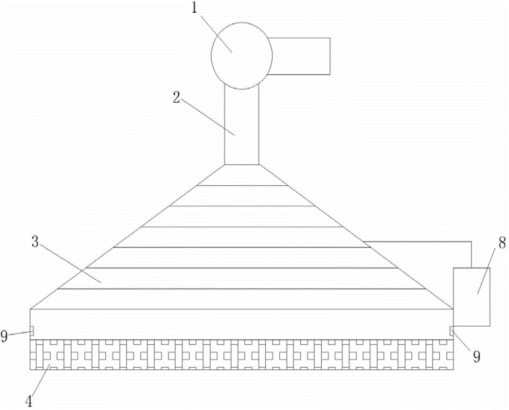
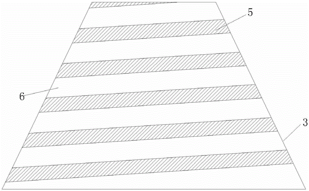
[0018] see figure 1 , figure 2 and image 3 , the suction hood device of the cotton catching machine described in the present invention, comprises blower fan 1, cotton conveying pipe 2, suction cover 3, catches cotton beater 4; On the inner wall of described suction hood 3, a plurality of spirally arranged air guide strips 5 are formed , there is a groove 6 between the two adjacent air guiding strips 5, and an electromagnet 7 is arranged on the groove 6, and the electromagnet 7 is connected with the controller 8; on the inner wall of the suction cover 3 A photoelectric sensor 9 is provided. In this embodiment, two photoelectric sensors 9 are respectively arranged on th...


PUM


Abstract

The invention relates to the technical field of textile machines, in particular to a suction cowl device of a plucker. The suction cowl device of the plucker comprises a fan, a cotton delivery pipe, a suction cowl and a plucking beater; a plurality of air guide strips spirally arranged are formed on the inner wall of the suction cowl; a groove is formed between every two air guide strips; each groove is provided with electromagnets; the electromagnets are connected with a controller; the inner wall of the opening of the suction cowl is provided with a photoelectric sensor; the photoelectric sensor is electrically connected with the controller. The invention provides the suction cowl device of the plucker, which is high in cotton suction efficiency, and is capable of removing sheet iron in cotton so as to prevent the cotton delivery pipe from being blocked and damaged.

Description

Technical field: [0001] The invention relates to the technical field of cotton spinning machinery, in particular to a suction cover device of a cotton grabbing machine. Background technique: [0002] Cotton spinning is the yarn processed by cotton fiber through spinning process, which becomes cotton thread after plying. Cotton plucking machine, also known as automatic cotton feeding machine, is the first stand-alone machine of feeding, opening and mixing machines. The cotton catching machine breaks up the cotton raw materials through the catching beater and then transports them to the next process through the fan for processing. The suction cover of the existing cotton catching machine is located above the cotton catching beater, and the cotton block enters through the suction effect of the fan. Cotton delivery pipes, but the traditional suction hood structure is not concentrated enough to absorb wind, and the efficiency of absorbing cotton blocks is low; iron fragments are...

Claims


Application Information

Patent Timeline
IPC IPC(8): D01G7/06
CPCD01G7/06
Inventor 陈永林
Owner 桐乡市建春塑业股份有限公司
Learn More