Gas cylinder type sewing machine

A sewing machine and cylinder type technology, which is applied to sewing machine components, sewing equipment, cloth feeding mechanisms, etc., can solve the problems of difficulty in adjusting the speed of the hem of the sewing needle, deterioration of the sewing quality, and wrinkles of the fabric, so as to suppress loosening and prevent seam opening. , the effect of reducing the pin spacing

Inactive Publication Date: 2015-06-03
MORIMOTO MFG
View PDF2 Cites 1 Cited by
  • Summary
  • Abstract
  • Description
  • Claims
  • Application Information

AI Technical Summary

Problems solved by technology

Therefore, there is a problem that, due to differences in the stretchability, thickness, material, etc. of the cloth, there is a hem that can adjust the speed with the pair of upper intermittent feed rollers and lower intermittent feed rollers, and the sheet does not move at an appropriate speed. If it moves, the fabric will wrinkle or loosen, which will lead to a decrease in the quality of the sewing process
Therefore, it is difficult to adjust the speed of the hem around the needle dropping position of the sewing needle depending on the stretchability, thickness, material, etc. of the fabric.
Therefore, the hem may not be conveyed at an appropriate speed, and the fabric may become wrinkled or slack, resulting in a decrease in the quality of the sewing process.

Method used


Image

  • Gas cylinder type sewing machine
  • Gas cylinder type sewing machine
  • Gas cylinder type sewing machine

Examples


Embodiment Construction

[0047] Preferred embodiments of the present invention will be described with reference to the drawings.

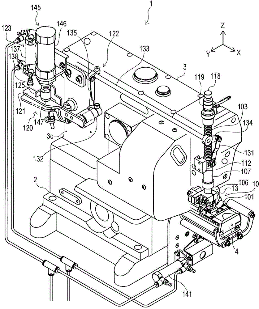
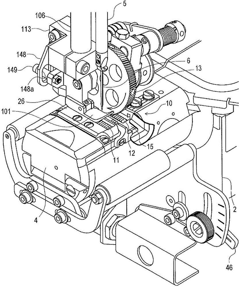
[0048] figure 1 A perspective view of the air cylinder sewing machine 1 according to one embodiment of the present invention is shown with a part of the arm portion 3 exposed for describing the details of the drive mechanism 70 of the intermittent feed roller 13 to be described later. figure 2 A perspective view of a sewing portion of the air cylinder sewing machine 1 is shown.

[0049] In addition, in the following, the arrow X direction in the figure is taken as the left direction of the air cylinder sewing machine 1, the arrow Y direction is taken as the rear direction of the air cylinder sewing machine 1, and the arrow Z direction is taken as the upper direction of the air cylinder sewing machine 1. .

[0050]Such as figure 1 and figure 2 As shown, the air cylinder sewing machine 1 has a pedestal 2, the arm 3 connected to one end (right end) of the pedestal 2 in ...


PUM


Abstract

The invention provides a gas cylinder type sewing machine which is capable of obtaining fine processing in sewing of a barrel-shaped lower hem of a multi-layer folding clothing material. A clothing material feeding mechanism for the gas cylinder type sewing machine comprises a first feeding tooth which is arranged at one side of a needle dropping position of a sewing needle of a gas cylinder part and capable of conveying a sheet part along a clothing material feeding direction from one resisting side of the sheet body and the below, a second feeding tooth which is arranged at one side reverse to one side of the first feeding tooth opposite to the needle dropping position of the sewing needle and capable of conveying the lower hem along the clothing material feeding direction from one resisting side of the lower hem and below, and an intermittent feeding roller which is arranged at the side of the sewing needle in a mode of moving up and down and capable of intermittently conveying the lower hem in the clothing material feeding direction from the above and one resisting side of the lower hem; The gas cylinder type sewing machine can be regulated through the feeding amount of the sheet conveyed by the first feeding tooth, the feeding amount of the lower hem conveyed by the second feeding tooth and the feeding amount of the lower hem conveyed by the intermittent feeding roller.

Description

technical field [0001] The present invention relates to a cylinder type sewing machine for sewing tubular parts of clothes such as trouser hems. Background technique [0002] A cloth feeding device of a sewing machine is known, comprising a sewing needle and a pair of upper and lower intermittent feed rollers arranged on the side of the sewing needle, and the cloth feeding device can use mutual The pair of upper and lower intermittent feed rollers rotating at different rotation speeds presses the cloth while conveying the cloth to the bottom of the sewing needle, thereby performing three layers of hem on the hem of the trousers. Rolled hemmi (For example, refer to Patent Document 1 and Patent Document 2.). [0003] However, in the cloth feeding device of the sewing machine, the pair of upper intermittent feed rollers and the lower intermittent feed rollers only convey the hem that forms a three-layer hem while pinching, so the piece connected with the hem is only Move with...

Claims


Application Information

Patent Timeline
Patent Type & Authority Applications(China)
IPC IPC(8): D05B27/02
CPCD05B27/02
Inventor 松崎博史细川真人福井茂俊村上智纪
Owner MORIMOTO MFG
Why Eureka
Try Eureka