[0003] The technical problem to be solved by the present invention is to overcome the defects of the prior art. The present invention provides a CNC cutting
machine tool for sheet metal processing. After the power is turned on, press the switch button to allow the power supply box to start supplying power to the inside of the CNC cutting
machine tool. , press the switch button of the
drive motor to start the
drive motor, and the start of the
drive motor will drive the
vacuum cleaner to start running, and the
vacuum cleaner can collect the
metal debris produced after the plate is processed, so that the
metal debris will not fly freely , so as to avoid the
pollution caused by
metal debris, to a certain extent, it plays a role in protecting the environment, so that the entire CNC cutting machine can start running, and then the plate to be processed is taken out and placed in the
normal position of the arc cutting mechanism Below, then insert the
USB into the
USB interface to transmit the
graphics that need to be cut to the console, and the
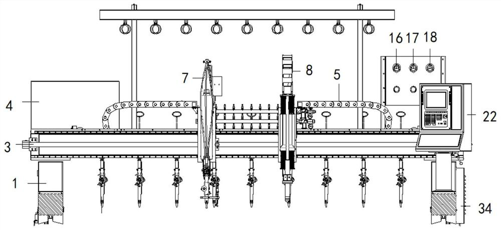
USB interface plays the role of transmission, and transmit the patterns that need to be processed to the console, so that the CNC cutting machine can be used to process exquisite plates , and then control the movement of the first chain on the track in the chain control key, and the movement of the first chain will drive the movement of the arc cutting mechanism until the arc cutting mechanism moves to the position where the arc cutting operation is required in the plate; check The pressure values in the
combustion gas pressure gauge, preheating
oxygen pressure gauge and cutting
oxygen pressure gauge, if the values in the
combustion gas pressure gauge, preheating
oxygen pressure gauge and cutting
oxygen pressure gauge do not reach the value of the processed plate, and the
combustion gas pressure If the gauge, preheating
oxygen pressure gauge and cutting
oxygen pressure gauge do not reach the value of the cutting plate, the cut plate cannot be used. When the combustion gas pressure gauge, preheating oxygen pressure gauge and cutting oxygen pressure gauge reach the value of the cutting plate, it can be Let the CNC cutting machine tool process the metal plate, so as to wait for the exquisite plate parts, then rotate the cutting oxygen pressure regulating knob, preheating oxygen pressure regulating knob and combustion gas pressure regulating knob until the combustion gas pressure gauge, preheating oxygen pressure The pressure value in the meter and the cutting oxygen pressure gauge reaches the value of the processed plate; at this time, use the control arc cutting mechanism in the arc cutting and
punching control key to touch the processed plate, and then open the three first valves, and the three The first valve plays the role of controlling the delivery of combustion gas, preheating oxygen and cutting oxygen to the first ventilation
pipe, so as to determine whether the arc cutting mechanism performs arc cutting operation on the plate. At the same time, you can watch the combustion gas pressure gauge and preheating oxygen pressure gauge. and whether the value in the cutting oxygen pressure gauge has reached the value of the processed plate, and use the pipeline control key to control the combustion
gas pipeline, preheating oxygen pipeline and cutting oxygen pipeline to deliver combustion gas, preheating oxygen and cutting oxygen to the first ventilation pipeline, So that the arc cutting mechanism can perform arc cutting operation on the plate to be processed, so that the plate to be processed can be formed; when the processed plate is formed, use the chain control key to control the movement of the first chain on the track, and with the first The movement of the chain will drive the movement of the
punching mechanism until the punching mechanism moves to the position where the punching operation needs to be performed in the plate, and then use the chain control key to control the second chain so that the punching
nozzle in the punching mechanism touches the The plate that needs to be processed, and the first chain can control the left and right movement of the arc cutting mechanism and the punching mechanism, while the second chain can control the punching mechanism. The lifting function of the hole mechanism; when the punching
nozzle touches the plate to be processed, use the pipeline control key to control the combustion
gas pipeline, preheating oxygen pipeline and cutting oxygen pipeline to deliver combustion gas, preheating oxygen and cutting oxygen to the delivery
pipe, In this way, the punching nozzle can punch holes on the sheet to be processed, and the punching nozzle can compress the combustion gas, preheating oxygen and cutting oxygen to form a powerful cutting
flame, thereby performing arc cutting on the
metal sheet. At this time, move the plate that has been drilled to the bottom of the nine drilling mechanisms; when the plate moves to the bottom of the nine drilling mechanisms, use the drilling control key to control the nine drilling mechanisms, and the nine
drill The hole mechanism moves to the position where the hole needs to be drilled in the plate, and the nine drilling mechanisms can perform subtle drilling operations on the metal plate, thereby avoiding some 0.35mm-1mm drilling holes that cannot be cut out by arc cutting operations alone When the situation occurs, use the pipeline control key to control the combustion
gas pipeline, preheating oxygen pipeline and cutting oxygen pipeline to deliver combustion gas, preheating oxygen and cutting oxygen to the second ventilation pipeline, so that the drilling nozzle can
drill the plate, In this way, the plate to be processed is processed into the forming
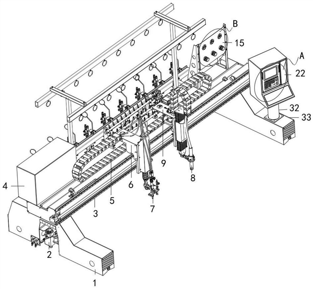
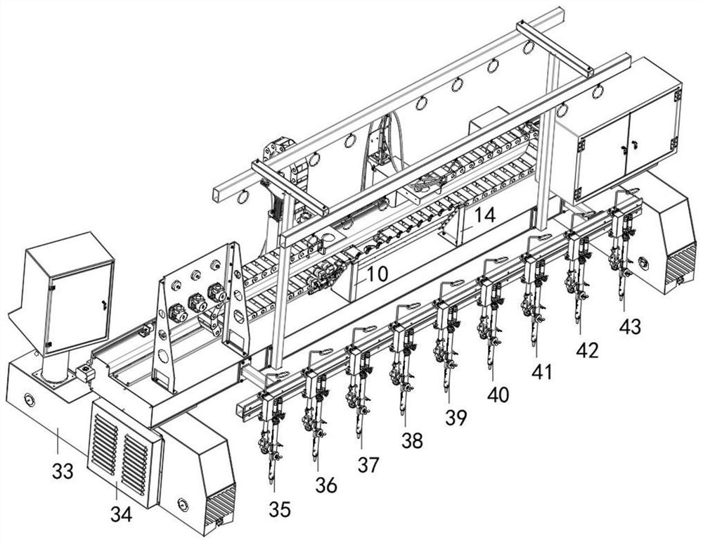
graphics standard transmitted in the console, and then the switch button is pressed to disconnect the power supply, and the operation is completed, and the switch button can disconnect the power supply from the power box to the inside of the CNC cutting machine, thereby enhancing the operation Safety of CNC cutting machine during operation; arc cutting mechanism, punching mechanism, first drilling mechanism, second drilling mechanism, third drilling mechanism, fourth drilling mechanism, fifth drilling mechanism in the present invention mechanism, the sixth drilling mechanism, the seventh drilling mechanism, the eighth drilling mechanism, the ninth drilling mechanism, the console and the design of the
vacuum cleaner can perform drilling operations in the range of 0.35mm-1mm on the plate, so that some Drilling holes in the range of 0.35mm-1mm are cut out of the plate that cannot be cut by the arc cutting operation, which makes the plate processing more exquisite, and avoids the high-temperature melting around the drilling holes in the range of 0.35mm-1mm cut by the arc cutting operation.
Metal pimples caused the failure of sheet metal processing, and at the same time accelerated the processing rate of sheet metal to a certain extent, and saved a lot of time, which solved the problem mentioned in the above background technology.
Cutting machine tools all use a nozzle to process the plate, which reduces the speed of plate processing to a certain extent, and also consumes a lot of time. Moreover, the current CNC cutting machine tools for metal plate processing basically use arc cutting operations, but in this way For example, some
drill holes in the range of 0.35mm-1mm cannot be cut out by arc cutting alone. Even if the drill holes in the range of 0.35mm-1mm are cut out, there are metal bumps that have been melted at high temperature. And these metal bumps may cause the problem of plate processing failure

