Adjustable mechanical self-locking hydraulic cylinder

A mechanical, hydraulic cylinder technology, applied in the field of hydraulic actuators, can solve the problems that can not meet the long-term, high-precision locking, good safety performance, and high positioning requirements

Inactive Publication Date: 2015-06-03
XUZHOU AOBO MACHINERY TECH
View PDF5 Cites 5 Cited by
  • Summary
  • Abstract
  • Description
  • Claims
  • Application Information

AI Technical Summary

Problems solved by technology

For the use of hydraulic locking sleeves in the cylinder, the locking method can lock the load force is not large, it needs high-pressure oil to unlock, and once the oil leaks, it cannot meet the long-term and high-precision locking
For the locking method that uses a bolt mechanism or a pad to fix the piston rod, the bolt or pad needs to be manually moved, and the operation is relatively cumbersome
[0004] In view of the wide range of applications of hydraulic cylinders and the shortcomings of the existing main hydraulic locking methods, when the hydraulic cylinder needs to be locked for a long time in a certain position, the positioning requirements are high, and the safety performance is good, such as aerospace occasions, hydraulic locks and other methods are used. it is difficult to meet the requirements

Method used


Image

  • Adjustable mechanical self-locking hydraulic cylinder
  • Adjustable mechanical self-locking hydraulic cylinder

Examples


Embodiment Construction

[0011] The present invention will be further described below in conjunction with the accompanying drawings and embodiments.

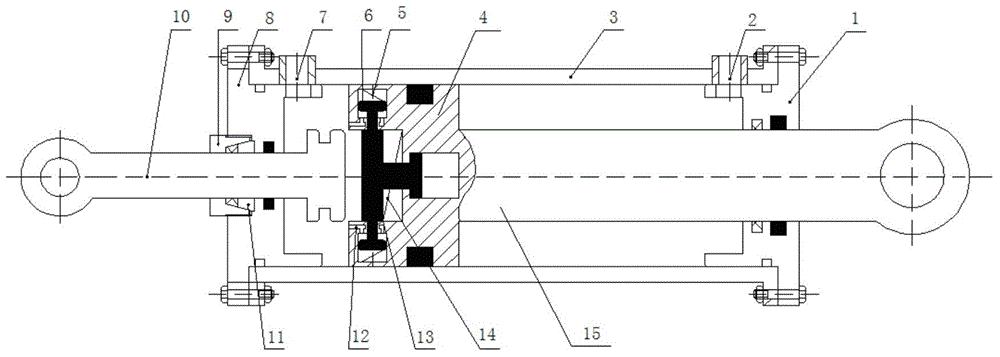
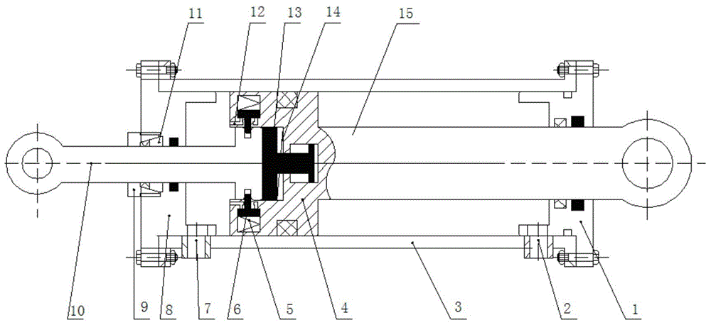
[0012] Such as figure 1 As shown, an adjustable mechanical self-locking hydraulic cylinder has a cylinder 3 with openings at the front and rear ends, a piston 4 matching the inner wall of the cylinder is installed in the cylinder 3, a piston rod 15 is installed on the piston 4, and the cylinder The front end of barrel 3 is detachably installed a front end cover 1, and the rear end of cylinder barrel 3 is detachably installed a rear end cover 8, and piston rod passes through front end cover and stretches out cylinder barrel 3; The oil inlet 2 is provided with an oil outlet 7 on the cylinder wall close to the rear end cover 8, and a central through hole is provided in the center of the piston 4, and a positioning baffle 13 and a baffle spring 14 are installed in the central through hole to position The baffle plate 13 is slidingly matched with the surfac...


PUM


Abstract

The invention discloses an adjustable mechanical self-locking hydraulic cylinder and relates to a hydraulic executing element. The adjustable mechanical self-locking hydraulic cylinder is provided with a cylinder barrel; a piston is mounted in the cylinder barrel; a piston rod is mounted on the piston; front and rear end covers are correspondingly mounted at the front and rear ends of the cylinder barrel in a detachable manner; oil inlet and outlets are formed on the wall of the cylinder barrel; a center through hole is formed at the center of the piston rod; a positioning baffle and a baffle spring are mounted in the center through hole; the positioning baffle is in sliding fit with the surface of the center through hole; grooves are symmetrically formed on the inner wall of the front end of the center through hole; locking blocks are arranged in the grooves; locking block springs are arranged between the locking blocks and the bottom ends of the grooves; a lock rod is mounted in a head port; one end of the lock rod extends out of the rear end cover; clamping grooves are symmetrically formed up and down at the other end of the lock rod; the bottom end of the locking blocks are matched with the clamping grooves; a locking device is arranged at the joint of the lock rod and the rear end cover; oil inlet small holes are symmetrically formed on the wall of the piston end close to the rear end cover. By the mechanical self-locking structure of the adjustable mechanical self-locking hydraulic cylinder, a self-locking function is implemented at the corresponding position, so that the application range of the hydraulic cylinder is further widened.

Description

technical field [0001] The invention relates to a hydraulic actuator, in particular to an adjustable mechanical self-locking hydraulic cylinder, which has the function of realizing self-locking at different positions, and is high in precision, safe and reliable, and can keep locking for a long time. . Background technique [0002] Hydraulic transmission is widely used in agricultural machinery, engineering machinery, aerospace and other occasions because of its high power density, easy to realize stepless speed regulation, standardization, and high degree of automation. As one of the important executive components of the hydraulic system, the hydraulic cylinder is almost one of the essential components in all hydraulic transmission systems. It is an important means to realize reciprocating motion in the hydraulic system, which is also one of the important advantages of hydraulic transmission over mechanical transmission. . In some occasions, the actuator needs to be fixed ...

Claims


Application Information

Patent Timeline
Patent Type & Authority Applications(China)
IPC IPC(8): F15B15/20F15B15/26
CPCF15B15/20F15B15/261
Inventor 邓海顺李刚骆支宝
Owner XUZHOU AOBO MACHINERY TECH
Why Eureka
Try Eureka