Supercharge Your Innovation With Domain-Expert AI Agents!

Hydraulic flat valve

A flat valve, hydraulic technology, applied in sliding valve, valve details, valve device and other directions, can solve the problems of high economic cost, unsatisfactory effect, valve can not withstand severe cold weather, buffer liquid pressure and external pressure, etc., to ensure smooth operation. The effect of preventing the force area from being too small

Inactive Publication Date: 2015-06-03
CHENGDU LYUDI TECH
View PDF5 Cites 0 Cited by
  • Summary
  • Abstract
  • Description
  • Claims
  • Application Information

AI Technical Summary

Problems solved by technology

The means of treatment are also from the original packaging to the development of the latest materials, but whether the effect is not ideal or the economic cost is too high, the problems of valves not being able to withstand severe cold weather, buffer liquid pressure and external pressure are still outstanding.

Method used


Image

  • Hydraulic flat valve

Examples


Embodiment Construction

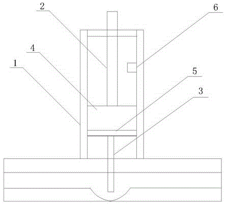
[0012] Such as figure 1 As shown, a hydraulic plate valve of the present embodiment includes a valve body 1, a valve stem 2 and a valve plate 3, the valve body 1 is provided with a space for accommodating the valve stem 2 and the valve plate 3, and the valve body 1 is additionally supplied with liquid or channels through which gases pass. The valve stem 2 is provided with a thread matched with the valve body 1, and the valve stem 2 and the valve body 1 rotate relative to each other through the thread, so that axial displacement occurs. The valve body 1 is provided with a hydraulic cavity 4, and the valve stem 2 is located in the hydraulic cavity 4 and sealed with the hydraulic cavity 4 by a sealing ring. The valve stem 2 and the valve plate 3 are connected by a pressure plate 5 , the pressure plate 3 is located at the bottom of the hydraulic chamber 4 , and the valve plate 3 is located at the bottom of the pressure plate 5 .

[0013] The hydraulic chamber 4 is in sealing con...


PUM


Abstract

The invention discloses a hydraulic flat valve. The hydraulic flat valve comprises a valve body, a valve rod and a valve plate, wherein space for accommodating the valve rod and the valve plate is formed in the valve body; the valve rod is provided with threads which are matched with the valve body; a hydraulic cavity is formed in the valve body; the valve rod is positioned in the hydraulic cavity and is connected with the valve plate through a pressure plate; the pressure plate is positioned on the bottom of the hydraulic cavity; and the valve plate is positioned on the bottom of the pressure plate. According to the technical scheme, the impact force of the outside on the flat valve can be buffered, and the hydraulic flat valve can work normally in a severe environment.

Description

technical field [0001] The invention relates to the field of mechanical valves, in particular to a hydraulic plate valve. Background technique [0002] Valves are very important components in controlling pipeline transportation and liquid flow operations. Especially in oil pipelines and natural gas pipelines, the pipelines are under great pressure, and the sealing and pressure resistance of valves determine the safety performance of pipeline transportation. The valves in the existing pipelines are mechanical valves, and the opening and closing of the valves are completed by a threaded rotating mechanism, and manual operation is required. However, in harsh environments, such as plateau areas and alpine areas, valves need special treatment to prevent corrosion and freezing of valves, and accidents occur during maintenance and emergency handling. The means of treatment are also from the original packaging to the development of the latest materials, but whether the effect is n...

Claims


Application Information

Patent Timeline
Patent Type & Authority Applications(China)
IPC IPC(8): F16K3/02F16K31/122
CPCF16K3/02F16K3/32F16K27/044F16K31/122
Inventor 梁枫
Owner CHENGDU LYUDI TECH
Features
  • R&D
  • Intellectual Property
  • Life Sciences
  • Materials
  • Tech Scout
  • Unparalleled Data Quality
  • Higher Quality Content
  • 60% Fewer Hallucinations
Learn More