Condensate heat recovery method using double flashing and pressurizing

A recovery method and condensed water technology, applied in lighting and heating equipment, steam generation, etc., can solve the problems of low heat utilization rate and energy waste of condensed water, and achieve the effects of wide application, high steam value and simple process flow

Inactive Publication Date: 2015-06-03
张高博
View PDF5 Cites 6 Cited by
  • Summary
  • Abstract
  • Description
  • Claims
  • Application Information

AI Technical Summary

Problems solved by technology

[0004] The purpose of the present invention is to solve the problem of low heat util

Method used


Image

  • Condensate heat recovery method using double flashing and pressurizing

Examples


Embodiment 1

[0016] Example 1: Modification of the condensed water heat recovery system in a catalytic cracking unit of an oil refinery.

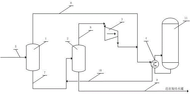
[0017] Such as figure 1 As shown, the original process is that high-temperature condensate 5 with a pressure of 0.6 MPaG and a flow rate of 40 t / h directly enters the condensate tank. After the transformation, the high-temperature condensate 5 enters the primary flash tank 1 first, and the primary flash steam 6 with a pressure of 0.3MPaG is flashed out, and the primary condensed water 7 enters the secondary flash tank 2 for secondary flash evaporation, and the flash pressure is The secondary flash steam 8 of 0.1MPaG, the secondary flash steam 8 enters the vapor compression equipment 3, the pressure after compression is 0.3MPaG, and the primary flash steam 6 of the same pressure enters the heat exchanger 4 together to provide a heat source for the separation tower 11. The heated condensate 10 and the primary condensate 7 are used as the feed of the seconda...


PUM


Abstract

The invention relates to a condensate heat recovery method using double flashing and pressurizing and aims to solve the problem that in the traditional techniques, condensate heat is greatly wasted. By introducing a two-stage flashing technique and a vapor compression technique, heat in condensate can be recycled in the form of low-pressure vapor; the method is suitable for recovering the heat of vapor condensate at the temperature lower than 190 DEG C and under the pressure lower than 1.0 MPaG. The method includes the steps of primary flashing of condensate, secondary flashing and pressurizing, and returning and reusing of condensate occurring after flash steam heats medium. The method has the advantages that energy recovery rate is high and vapor value is high.

Description

Technical field [0001] The invention relates to a method for recovering the heat production of condensed water with two flashing and pressure raising. It is suitable for recovering the heat of condensed water whose temperature is below 190℃. The use occasion is generally in various process industrial devices that may generate steam condensate, which belongs to the field of energy saving technology. Background technique [0002] In the process industry, water vapor is widely used to heat materials. During the heating process, the water vapor releases its latent heat to produce condensed water. The temperature of condensed water is generally close to the saturation temperature of the steam used, generally greater than 100°C, and the thermal energy value accounts for about 5-15% of the steam thermal energy value. [0003] The degree of recovery and utilization of condensate heat is an important factor affecting the energy efficiency of the device. In the traditional process, high-t...

Claims


Application Information

Patent Timeline
IPC IPC(8): F22B3/04
Inventor 张高博
Owner 张高博
Why Eureka
Try Eureka