Bone incinerating equipment

A technology of equipment and cremated ashes, which is applied in the field of cremated ashes burning equipment, can solve the problems of dust formation, high impurity content, and increased process, so as to reduce the size of materials, ensure the effect of incineration, and prolong the service life.

Inactive Publication Date: 2015-06-03
ZHEJIANG SCI-TECH UNIV
View PDF6 Cites 0 Cited by
  • Summary
  • Abstract
  • Description
  • Claims
  • Application Information

AI Technical Summary

Problems solved by technology

However, in the current process of incinerating animal carcasses, there are several major shortcomings: it is easy to produce a large amount of solid particles, thereby forming smoke and dust, which has an adverse effect on the surrounding environment; because of centralized incineration, the incineration process is prone to insufficient phenomena , the utilization rate of raw materials is limited and the content of impurities will be too high; and due to incomplete combustion, there are more impurities and residual materials in the product, which requires subsequent treatment, which increases the process and has a negative impact on production efficiency and cost

Method used


Image

  • Bone incinerating equipment
  • Bone incinerating equipment
  • Bone incinerating equipment

Examples


Embodiment 1

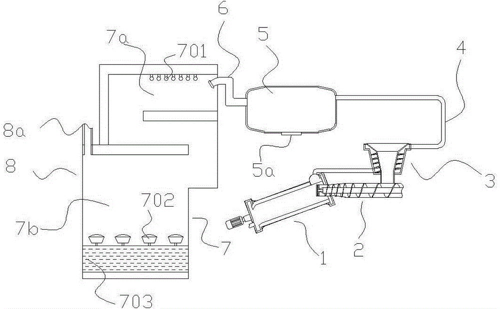
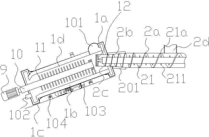
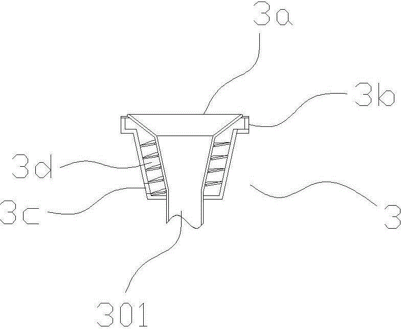
[0023] like figure 1 , figure 2 , image 3 In the shown embodiment 1, a kind of inorganic phosphate fertilizer manufacturing device comprises incinerator 1, feeding device 2, smoke cleaning device 7 and preheating device 3; Incinerator comprises furnace body 1b, furnace head 1a and furnace tail 1c, The incinerator is arranged obliquely, and the height of the furnace head is higher than that of the furnace tail. There is an incineration chamber 1d inside the furnace body, combined with figure 2 As shown, the incineration chamber is provided with a transmission main shaft 10 driven by the main motor 9, and a plurality of bulk materials 11 for moving materials are arranged on the transmission main shaft. The bulk materials are in a hollow tubular structure, along the diameter of the transmission main shaft Arranged in the direction, it also includes an air pump that can blow air into the inner cavity of the main shaft, and the central through hole of the bulk body communicat...

Embodiment 2

[0031] The basic structure and implementation mode of this embodiment are the same as embodiment 1, and its difference is, as Figure 4 Shown, also comprise a cleaning motor, the transmission main shaft is provided with the main shaft inner chamber, and a transmission inner shaft 17 coaxial with the transmission main shaft stretches among the main shaft inner chamber. One end of the transmission inner shaft can be driven to rotate by the output shaft of the cleaning motor, and the other end is connected with the bearing of the inner shaft, and multiple cleaning devices are arranged on the transmission main shaft. The dirt removal device comprises a dirt ball 18, a limit ball 19, a ball receiving spring 16, a slide bar 15, a slide hole arranged on the drive shaft wall, the slide bar and the slide hole are slidably matched, and the dirt ball and the limit ball are respectively connected with the The two ends of the slide rod are connected, and the ball receiving spring is set on...


PUM


Abstract

The invention discloses bone incinerating equipment comprising an incinerator, a feeder, a smoke purifier and a preheater. The feeder is used for feeding materials into the incinerator. The smoke purifier is used for purifying hot smoke discharged by the incinerator. The incinerator comprises a body, a head and a tail; an incinerating chamber in the body is provided with a transmission spindle driven by a main motor; the transmission spindle is provided with a plurality of scattering members used for stirring the materials. The feeder comprises a feed cylinder extending into the incinerating chamber from a feed opening. A feed screw is disposed within the feed cylinder. The preheater comprises a preheating hopper and a spiral flue surrounding the preheating hopper. The smoke purifier comprises a discharge outer duct and a water receiver; a plurality of sprinklers are arranged in the upper portion of the inside of the discharge outer duct. The bone incinerating equipment has the advantages that animal corpses can be effectively centrally incinerated, the incinerating process is stable and efficient, sufficient incineration is guaranteed, produced smoke can be effectively treated, and smoke pollution can be avoided.

Description

technical field [0001] The invention relates to the field of burning ashes, in particular to burning equipment for burning ashes. Background technique [0002] At present, after the death of many wild animals, domestic animals and poultry, the dead bodies are often not processed in time. Among them, dead domestic animals and poultry, especially abnormally dead domestic animals and poultry, are often in large numbers. Disposal through landfill, and sometimes the disposal process is often more sloppy, such as directly into the river, which will cause a series of safety and social problems. For the disposal of animal carcasses by landfill, due to the large volume of animal carcasses, the decomposition is relatively slow, and it takes a long time to decompose and be converted into soil fertility. This will not only occupy more land resources, but also have poor actual fertilizer supply capacity. . Therefore, it can be selected to be incinerated centrally and burned into bone a...

Claims


Application Information

Patent Timeline
Patent Type & Authority Applications(China)
IPC IPC(8): F23G1/00F23J15/04F23J1/06
CPCF23G1/00F23G2900/7009F23J1/06F23J15/04F23J2217/50F23J2700/001
Inventor 孙永剑万昌江
Owner ZHEJIANG SCI-TECH UNIV
Why Eureka
Try Eureka