Supercharge Your Innovation With Domain-Expert AI Agents!

Direction control device, casing pipe conveying device and method and concentricity measuring device

A technology for direction control and transporting devices, applied in the direction of measuring devices, optical devices, instruments, etc., to achieve the effect of suppressing positional deviation

Inactive Publication Date: 2015-06-03
SEIKO INSTR INC
View PDF6 Cites 1 Cited by
  • Summary
  • Abstract
  • Description
  • Claims
  • Application Information

AI Technical Summary

Problems solved by technology

That is, the above steps are continuously repeated until the workpiece is oriented in a predetermined direction, so there is room for improvement in that it takes time to perform processing for oriented the workpiece in a predetermined direction.

Method used


Image

  • Direction control device, casing pipe conveying device and method and concentricity measuring device
  • Direction control device, casing pipe conveying device and method and concentricity measuring device
  • Direction control device, casing pipe conveying device and method and concentricity measuring device

Examples


Embodiment Construction

[0068] Hereinafter, embodiments of the present invention will be described with reference to the drawings.

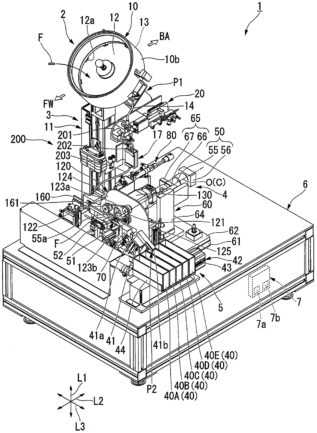
[0069] figure 1 It is a diagram showing an embodiment of the bushing concentricity measuring device of the present invention, and is a schematic configuration diagram of the whole.

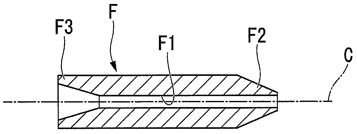
[0070] Such as figure 1 As shown, the bushing concentricity measurement device 1 of this embodiment is a device that photographs a plurality of bushings F (corresponding to "workpieces" in the claims) one by one, and performs bushing based on the captured images. The concentricity of F is measured and stored in the storage box 40 while being classified into quality grades based on the measurement results.

[0071] figure 2 yes figure 1 The overall perspective view of the casing concentricity measuring device shown.

[0072] The casing concentricity measurement device 1 includes: a casing supply device 2; a casing transport device 3 having a direction control device 20; a casing imagin...


PUM


Abstract

The invention provides a direction control device, a casing pipe conveying device and method and a concentricity measuring device, which enable work pieces to face a specified direction quickly. The direction control device (20) comprises a direction judging part (29) which judges the direction of a casing pipe (F) with a front end portion (F2) and a rear end portion (F3), and a casing pipe moving part (26) which retains the casing pipe (F) by using a retaining part (26a) and enables the casing pipe (F) to move toward either a first discharge opening (24) or a second discharge opening (25) according to the judging result of the direction judging part (29). The retaining part (26a) is formed in the up-down direction (L1).

Description

technical field [0001] The invention relates to a direction control device, a sleeve pipe delivery device, a sleeve pipe concentricity measuring device and a sleeve pipe delivery method. Background technique [0002] Conventionally, a ferrule has been used as a member for connecting optical fibers to each other while aligning the positions of the core wire end faces of the optical fibers. The ferrule is a cylindrical member having a through hole formed along its central axis, and is attached to, for example, an optical connector component in a state where the core wire of an optical fiber is inserted into the through hole. Therefore, in order to connect the optical fibers while accurately aligning the positions of the core wire end faces, a high level of concentricity between the inner diameter and the outer diameter of the ferrule is required. [0003] The concentricity is generally defined as the magnitude of an error (positional deviation) between the center of a target ...

Claims


Application Information

Patent Timeline
IPC IPC(8): G01B11/27
Inventor 小林贤史
Owner SEIKO INSTR INC
Features
  • R&D
  • Intellectual Property
  • Life Sciences
  • Materials
  • Tech Scout
  • Unparalleled Data Quality
  • Higher Quality Content
  • 60% Fewer Hallucinations
Learn More