Adsorption-desorption apparatus and process

a technology of adsorption and desorption, applied in the direction of chemistry apparatus and processes, separation processes, dispersed particle separation, etc., can solve the problems of inefficiency of thermal cycling of one bed of sorbent material between adsorption and desorption cycles, cost and time consumption, etc., to achieve the effect of reducing the cost of method and time consumption

Inactive Publication Date: 2012-01-12
PRECISION COMBUSTION
View PDF3 Cites 34 Cited by
  • Summary
  • Abstract
  • Description
  • Claims
  • Application Information

AI Technical Summary

Benefits of technology

[0036]The above-described apparatus and adsorption-desorption process of this invention are advantageously employed to remove a target compound, for example, a bulk compound, a contaminant, or a trace compound, from a flowstream, and more advantageously, employed to provide a life-sustaining quality of cabin air in a spacecraft or in an astronaut's ventilation loop. Even more advantageously, as used in this invention the heat conductive foam having coated thereon a sorbent (referred to herein as the “sorbent structure”) offers the advantages of a lighter mass and smaller volume payload and greater structural stability as compared to packed pellet beds or packed foam beds of the prior art. Even more advantageously, the sorbent employed in this invention directly contacts a structural material of high thermal conductivity, herein the heat conductive foam, so that heat is quickly transported into or away from the material thereby assisting and improving desorption or adsorption, respectively.

Problems solved by technology

The prior art recognizes several disadvantages to conventional adsorption systems.
One method involves discarding the used sorbent material and replacing it with fresh sorbent; but this method is clearly too costly and time consuming.
Thermal cycling of one bed of sorbent material between adsorption and desorption cycles suffers from inefficiency, because the adsorption cycle is interrupted.
As a further disadvantage, the temperature and / or pressure conditions of the adsorption and desorption cycles may need to be maintained in narrow operating range(s), which may require a more complex control algorithm.
Furthermore, the more complex the system, the more likely the system will add considerable weight and cost to the adsorption process, a factor that is unacceptable in many applications, such as spacecraft and mobile applications.
While thermal and pressure swing adsorption-desorption processes offer certain advantages over single bed processes, the regeneration cycle is still problematic and inefficient.
On the other hand, heat transfer from the sorbent material to the heat conductive foam is not optimal.
The current state of the art carbon dioxide / water removal system onboard the International Space Station, for example, uses beds packed with solid sorbent pellets that are disadvantageously large in volume and mass.
More disadvantageously, the pellets are prone to break-down generating dust that clogs and contaminates the system.
Most disadvantageously, the thermal conductivity of such packed beds, typically molecular sieves, is inefficient, thereby increasing the power demands on heaters to assist the desorption process.

Method used


Image

  • Adsorption-desorption apparatus and process
  • Adsorption-desorption apparatus and process
  • Adsorption-desorption apparatus and process

Examples


example 1

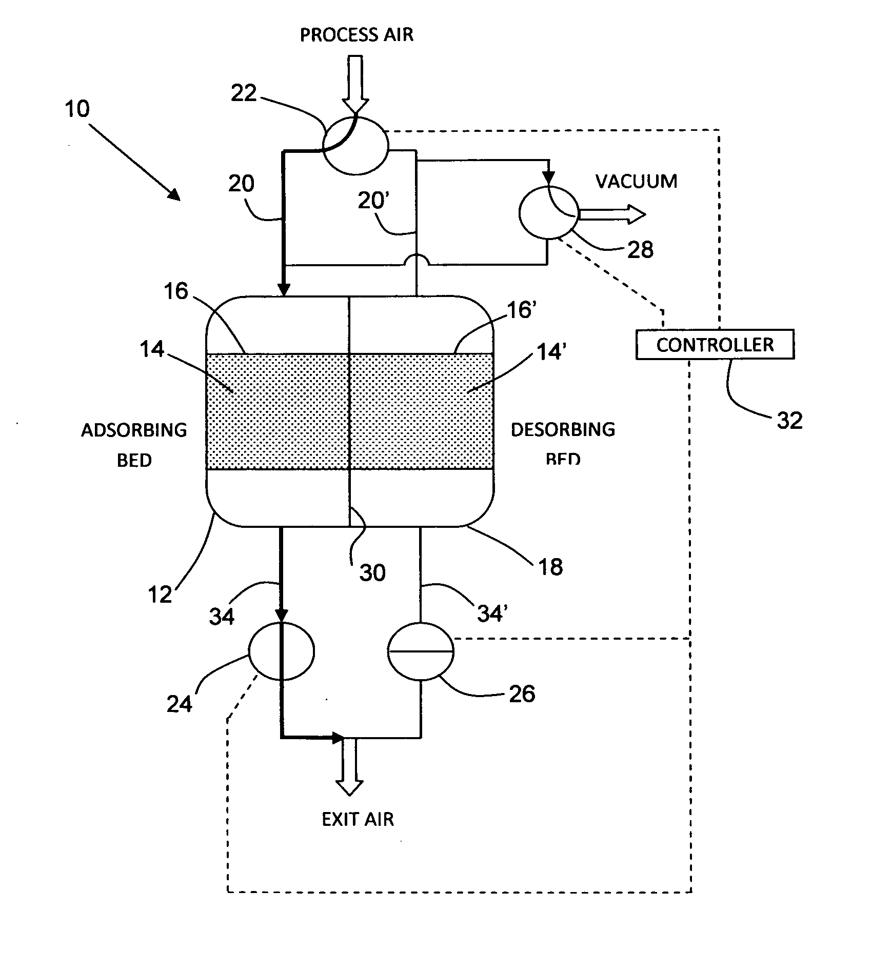
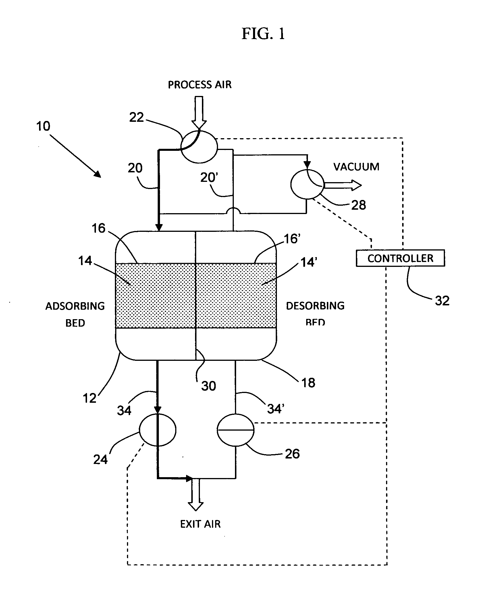
[0072]An adsorption-desorption apparatus according to the invention was constructed along the lines of FIG. 1. In this instance, the apparatus consisted of an aluminum housing into which were arranged 4 rectangular aluminum chambers, which for notation purposes were labeled chambers “A”, “B”, “C”, and “D”. The chambers were placed side-by-side with parallel flow paths, such that each chamber shared at least one common wall with an adjacent chamber. Each chamber was filled with an aluminum reticulated foam (ERG Materials and Aerospace Corporation), the foam being brazed onto the walls of each chamber for maximum heat transfer between the chambers. The reticulated aluminum foam had 40 pores per inch length (16 pores per cm length). Following assembly, the aluminum reticulated foam in each chamber was washcoated with a sorbent, specifically, zeolite 13X, and then dried. The zeolite sorbent loading was 1.4 g / in3 (85 mg / cm3), based on the free-standing aluminum foam exclusive of the hous...

example 2

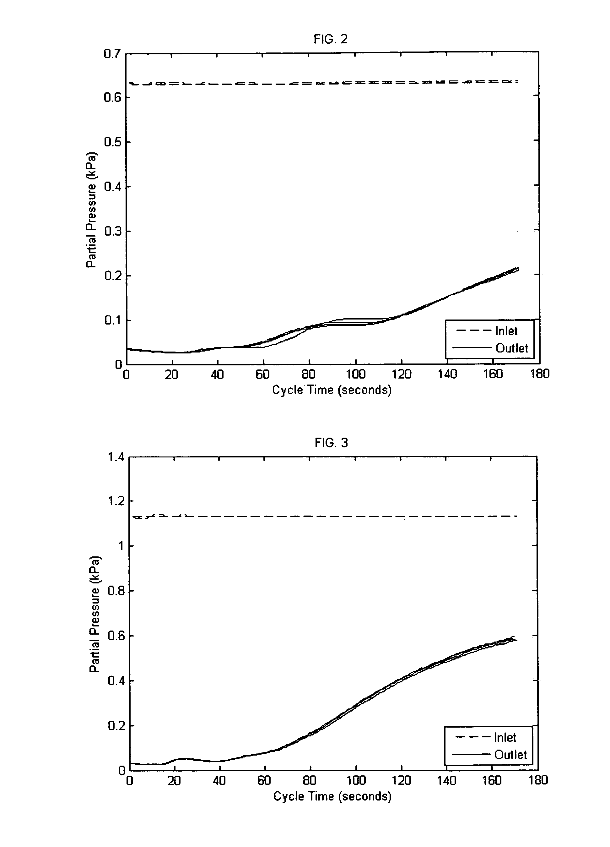
[0076]Example 1 was repeated with the following process conditions: inlet air flow rate was 10 slpm and the inlet water partial pressure was 1.133 kPa. A graph of water partial pressures in the inlet and outlet flowstreams versus time is shown for four overlaid half-cycles in FIG. 3. After operation for more than 40 half cycles, when reproducible cycles were observed, calculations over four half-cycles gave a result of 77.3 percent removal of water.

example 3

[0077]Example 1 was repeated with the following process conditions: inlet air flow rate was 10 slpm and the inlet water partial pressure was 1.630 kPa. A graph of water partial pressures in the inlet and outlet flowstreams versus time is shown for four overlaid half-cycles in FIG. 4. After operation for more than 40 half cycles, when reproducible cycles were observed, calculations over four half-cycles gave a result of 70.8 percent removal of water.


PUM

PropertyMeasurementUnit
total pressureaaaaaaaaaa
partial pressureaaaaaaaaaa
temperatureaaaaaaaaaa

Abstract

An apparatus and process for thermally-linked adsorption-desorption. The process involves (a) at least one pair of adjacent sorbent beds, referenced herein as first and second sorbent beds, each pair of adjacent beds being thermally-linked one to the other through a thermally conductive wall; wherein each sorbent bed comprises a heat conductive foam, such as a reticulated metallic foam or sponge, having a sorbent coated thereon; then (b) alternating a flowstream between the beds such that at least one bed operates in adsorption cycle to remove target compound(s) from the flowstream with generation of heat of adsorption, which is conductively transferred away from the first bed towards the second bed, while operating the second bed in desorption cycle to remove the adsorbed target compound(s).

Description

CROSS REFERENCE TO RELATED APPLICATION[0001]This invention claims the benefit of U.S. provisional patent application Ser. No. 61 / 399,245, filed Jul. 9, 2010.GOVERNMENT RIGHTS[0002]This invention was made with government support under Contract No. NNM06AB36C sponsored by the National Aeronautics and Space Administration. The U.S. Government holds certain rights in this invention.FIELD OF THE INVENTION[0003]This invention pertains to an apparatus and an adsorption-desorption process for removing one or more components from a flowstream. More specifically, this invention pertains to an apparatus and an adsorption-desorption process for removing one or more contaminants, such as carbon dioxide or a volatile organic compound (VOC), or removing another target compound, such as water, from a gaseous flowstream.[0004]The invention finds utility in any application wherein air quality needs to be upgraded by removing from the air a volatile compound hazardous to human health. Advantageously, ...

Claims


Application Information

Patent Timeline
Patent Type & Authority Applications(United States)
IPC IPC(8): B01D53/02B01D53/30
CPCB01D53/047B01D2253/108B01D2253/116B01D2253/20B01D2257/304B01D2257/406Y02C10/08B01D2257/708B01D2257/80B01D2259/40003B01D2259/40009B01D2259/40098B01D2259/4575B01D2257/504Y02C20/40
Inventor ROYCHOUDHURY, SUBIRJUNAEDI, CHRISTIANKNOX, JAMES
Owner PRECISION COMBUSTION
Why Eureka
Try Eureka