Portable scissor-lift-assembly

a scissor-lift and assembly technology, applied in the field of scissor-lift assemblies, can solve the problems of time and energy consumption, ladders or stools may become unstable, tilt, etc., and achieve the effect of raising and lowering

Inactive Publication Date: 2006-08-22
VAUGHAN BARRY +1
View PDF14 Cites 32 Cited by
  • Summary
  • Abstract
  • Description
  • Claims
  • Application Information

AI Technical Summary

Benefits of technology

[0011]The assembly includes a first platform provided with a planar top surface that has a centrally registered longitudinal axis. Such a first platform further has a pair of opposed sides equidistantly spaced from the longitudinal axis and traveling parallel thereto. The first platform includes a plurality of wheels and a plurality of brackets operably connected thereto wherein the wheels and the brackets extend outwardly from one of the sides and has an axis of rotation situated orthogonal thereto. Such wheels and brackets are spaced at opposed end portions of the platform. The assembly can be rotated about one side in such a manner that the wheels become operably engaged with a ground surface while the first and second platforms become oriented perpendicular to the ground surface and thereby advantageously allow the operator to quickly and readily transport the assembly between remote locations.
[0013]A pair of inverted U-shape guide rails are telescopically engageable along a longitudinal length of the support shafts. Each guide rail has a pair of monolithically formed rectilinear regions slidably positionable about the support shafts such that the guide rails can effectively be raised and lowered along a predetermined vertical path during operating conditions.

Problems solved by technology

Homeowners and small commercial contractors struggle with small interior and exterior projects that are at elevated heights, barely out of arms reach.
Unfortunately, the user must constantly travel up and down these structures to retrieve tools and materials, which is time and energy consuming.
Furthermore, the work area is limited to the reach of the user.
Such stepladders, stools, etc. place the user in an unsafe situation that may result in their falling from an elevated height.
For example, as the user leans to extend his reach, the ladder or stool may become unstable and tilt or the user may loose his grip or balance and fall to the ground.
This is very inefficient and wastes precious time and energy.
Stability of the structure is also an issue when working on unleveled surfaces, especially when working outdoors.
Such a lift's initial purchase cost is high with significant reoccurring maintenance costs.
The hydraulics require significant maintenance and constantly leak, making these machines unsuited for internal use for home or light industrial or small commercial operations.
The relative size of the available machines also limits their use to external areas or internal spaces with wide doorways and high ceiling not commonly found in homes.
Their use within a home or office is prohibited due to maneuverability through passageways and the leaking hydraulic fluid.
Most conventional aerial lifts are powered by diesel engines, propane motors or large battery packs, that also limits their usage within structures due to environmental issues.

Method used


Image

  • Portable scissor-lift-assembly
  • Portable scissor-lift-assembly
  • Portable scissor-lift-assembly

Examples


Embodiment Construction

[0027]The present invention will now be described more fully hereinafter with reference to the accompanying drawings, in which a preferred embodiment of the invention is shown. This invention may, however, be embodied in many different forms and should not be construed as limited to the embodiment set forth herein. Rather, this embodiment is provided so that this application will be thorough and complete, and will fully convey the true scope of the invention to those skilled in the art. Like numbers refer to like elements throughout the figures.

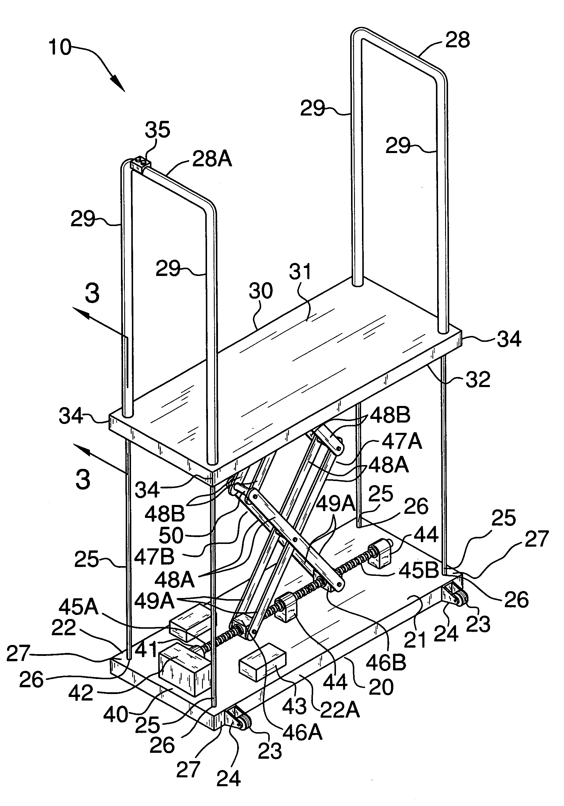
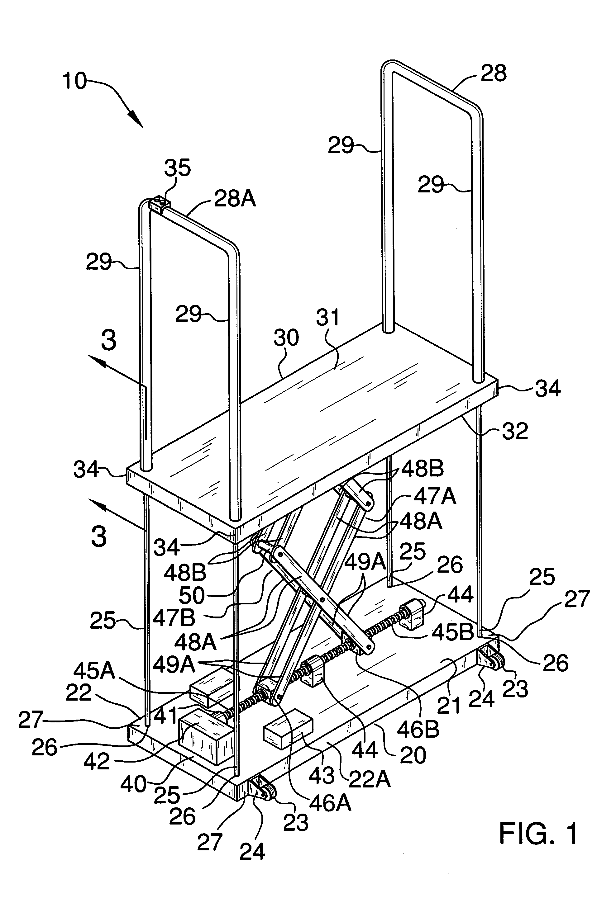
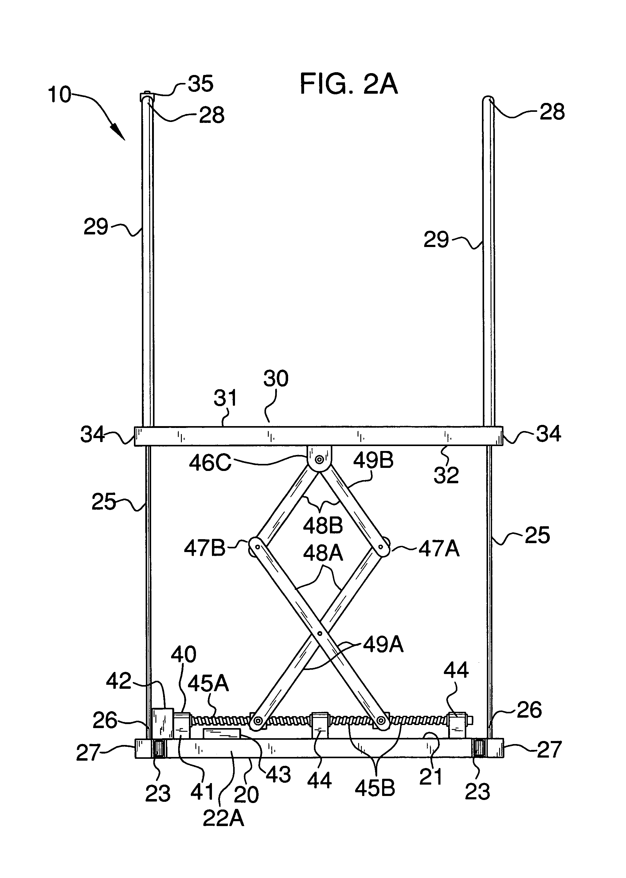
[0028]The assembly of this invention is referred to generally in FIGS. 1–4 by the reference numeral 10 and is intended to provide a scissor-lift assembly. It should be understood that the assembly 10 may be used to raise persons for many different types of applications and should not be limited in use to only home and small commercial applications.

[0029]Referring initially to FIG. 1, the assembly 10 includes a first platform 20 provided with ...


PUM


Abstract

A lift assembly includes a first platform provided with a top surface, a pair of opposed sides, and wheels and brackets connected to one of the sides for rotating the assembly. A plurality of rectilinear support shafts have opposed end portions conjoined to the platform and extending upwardly therefrom, and are spaced at opposed corners of the platform. Inverted U-shape guide rails are telescopically engageable along a length of the support shafts and have a pair of rectilinear regions slidably positionable about the support shafts. A second platform is provided with top and bottom surfaces, and apertures formed at opposed corners thereof that are vertically registered with the support shafts. A lifting mechanism is included for vertically biasing the second platform and the guide rails along the support shafts. The lifting mechanism is connected to the top surface of the first platform and the bottom surface of the second platform.

Description

CROSS REFERENCE TO RELATED APPLICATIONS[0001]Not Applicable.STATEMENT REGARDING FEDERALLY SPONSORED RESEARCH OR DEVELOPMENT[0002]Not Applicable.REFERENCE TO A MICROFICHE APPENDIX[0003]Not Applicable.BACKGROUND OF THE INVENTION[0004]1. Technical Field[0005]This invention relates to lift assemblies and, more particularly, to a scissor-lift assembly for lifting an operator along a vertical plane.[0006]2. Prior Art[0007]Homeowners and small commercial contractors struggle with small interior and exterior projects that are at elevated heights, barely out of arms reach. They primarily rely on stepladders, stools, and extension ladders for these projects. Unfortunately, the user must constantly travel up and down these structures to retrieve tools and materials, which is time and energy consuming. Furthermore, the work area is limited to the reach of the user. Such stepladders, stools, etc. place the user in an unsafe situation that may result in their falling from an elevated height. For ...

Claims


Application Information

Patent Timeline
Patent Type & Authority Patents(United States)
IPC IPC(8): B66B9/02
CPCB66B9/0815
Inventor VAUGHAN, BARRYVAUGHAN, ALVIN
Owner VAUGHAN BARRY
Why Eureka
Try Eureka