Torque test machine

A technology of torque testing and testing department, applied in the field of torque testing machines, can solve problems such as inaccurate test results, low test efficiency, and difficulty in applying force with a wrench, and achieve the effects of improving test efficiency, accurate torque value, and average torque

Inactive Publication Date: 2015-06-03
SICHUAN DITEL ELECTRONICS
View PDF0 Cites 3 Cited by
  • Summary
  • Abstract
  • Description
  • Claims
  • Application Information

AI Technical Summary

Problems solved by technology

However, the way the wrench rotates the combined tool head through the sleeve, because the sleeve does not receive any support and positioning, so the wrench exerts force more difficult and unstable
Moreover, the combined tool head is prone to slipping from the test portion or the sleeve, and therefore the test efficiency is not high and the test results are not accurate enough.

Method used


Image

  • Torque test machine
  • Torque test machine
  • Torque test machine

Examples


Embodiment Construction

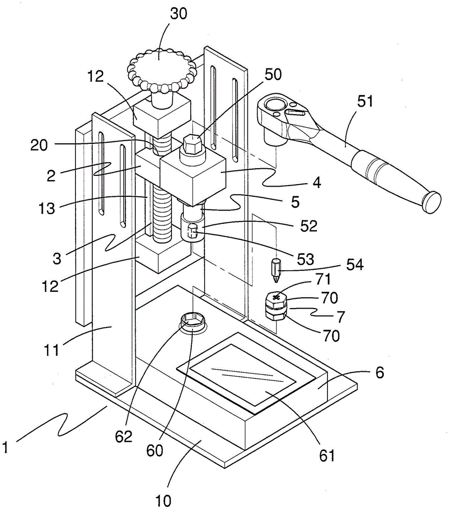
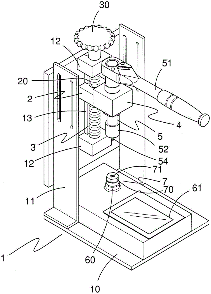
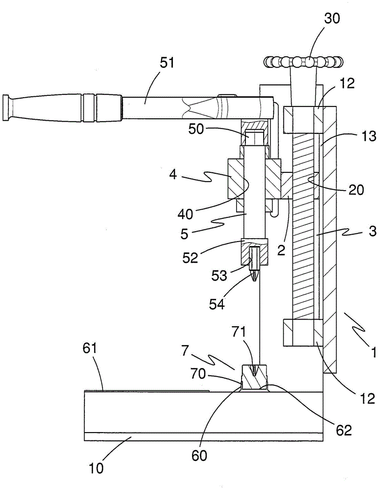
[0010] Such as Figure 1-3 It shows that the torque testing machine of the present invention includes a machine platform 1 , a movable block 2 , a lead screw 3 , a bump 4 , a shaft 5 , a torque testing device 6 and a jig 70 . Wherein: the machine table 1 has a base body 10 and a frame body 11 standing on the base body 10 . The frame body 11 has two fixing blocks 12 and a guide rail 13 on one side thereof. The two fixing blocks 12 are vertically separated by a certain distance, and the guide rail 13 is located between the two fixing blocks 12 and perpendicular to the base body 10 . The movable block 2 is movably combined with the guide rail 13 , and can move up and down between the two fixed blocks 12 . The movable block 2 has a threaded hole 20 through the upper and lower. The lead screw 3 is rotatably coupled to the two fixing blocks 12 perpendicular to the base 10 . The lead screw 3 passes through the screw hole 20 of the movable block 2 and is screwed into the screw hol...


PUM


Abstract

The invention discloses a torque test machine, which comprises a machine table, a movable block, a leading screw, a lug and a shaft, wherein the machine table is provided with a base a frame body standing on the base; the movable block can rise and fall relative to the base at one side of the frame body, and a screw hole is formed in the movable block; the leading screw is rotatably combined with the frame body, and is vertical to the base; the leading screw penetrates through the screw hole of the movable block, so that the leading screw can move through rotation; the lug is combined with the movable block; the shaft is rotatably combined with the lug, and is parallel with the leading screw; one end, which is far away from the base, of the shaft is provided with a drive part, and the drive part can be used for driven to rotate by a spanner; one end, which is near the base, of the shaft is provided a bell and spigot joint part; the shaft is controlled to rise and fall through the rotation of the leading screw. The torque test machine is very simple in operation, and very accurate in positioning; the test efficiency can be greatly increased.

Description

technical field [0001] The invention relates to a testing machine, in particular to a torque testing machine. Background technique [0002] The commonly used method for testing the torsion of a combined tool head of a hand tool is to embed a jig into the testing part of a torque tester, then insert one end of the combined tool head into the embedded hole of the jig, and A sleeve is used to cover the other end of the combined tool head, and a wrench is used to drive the sleeve to rotate until the combined tool head breaks, and the torque tester can show that the combined tool head can bear received torque value. However, the wrench rotates the combined tool head through the sleeve, because the sleeve does not receive any support and positioning, so the wrench exerts force more difficult and unstable. Moreover, the combined tool head is prone to slipping from the testing part or from the sleeve, which will lead to the problems of low testing efficiency and inaccurate testing...

Claims


Application Information

Patent Timeline
Patent Type & Authority Applications(China)
IPC IPC(8): G01L5/24
Inventor 雷勇王举帅娟
Owner SICHUAN DITEL ELECTRONICS
Why Eureka
Try Eureka