Confining pressure cylinder device for novel split Hopkinson pressure bar active confining pressure experiment

A Hopkinson compression rod and active technology, which is applied in the field of confining pressure cylinder device, can solve the problems of affecting the experiment, the rod is not pressed tightly to the test piece, etc., and achieves the effect of simple structure and reasonable design

Inactive Publication Date: 2015-06-03
LUOYANG LIWEI TECH
View PDF6 Cites 8 Cited by
  • Summary
  • Abstract
  • Description
  • Claims
  • Application Information

AI Technical Summary

Problems solved by technology

When the pressure chamber continues to pressurize, although the metal retaining ring prevents the rubber sleeve from deforming and enters the gap formed by the cover and the rod to drive the rod to move outward, it still cannot solve the problem of the high pressure causing the rubber sleeve to hold the rod tightly. At the same time, the force on the rod produces a tendency to move to the outside of the cavity, so that the rod cannot press the test piece tightly, so that the section of the rod that was originally in close contact with the test piece is no longer in contact with the test piece, leaving a gap, which affects experiment

Method used


Image

  • Confining pressure cylinder device for novel split Hopkinson pressure bar active confining pressure experiment

Examples


Embodiment Construction

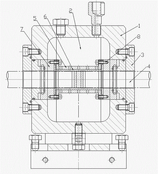
[0014] Such as figure 1 A new type of confining pressure cylinder device for active confining pressure experiment of Hopkinson pressure rod shown, including cylinder body 1, pressure chamber 2 in cylinder body 1, cylinder head 3, compression block 8, metal sleeve 6, rubber sleeve 5 and the shaft hole 4; the outer two ends of the cylinder body 1 are respectively provided with a cylinder head 3; the two ends of the pressure chamber 2 are respectively provided with a compression block 8 corresponding to the cylinder head 3, and one end of the compression block 8 extends into the cylinder Inside the body 1; a metal sleeve 6 is provided between the compression blocks 8 at both ends of the pressure chamber 2, and is connected by screws 9; a rubber sleeve 5 is provided inside the metal sleeve 6, and the rubber sleeve 5 is located on both sides of the pressure chamber 2 Between the compression block 8 at the end, the compression block 8 is formed with the metal sleeve 6 and the rubber...


PUM


Abstract

The invention relates to an impact loading experimental device for material dynamic mechanical property, and in particular relates to a confining pressure cylinder device for a novel split Hopkinson pressure bar active confining pressure experiment. The confining pressure cylinder device comprises a cylinder body, a pressure cavity in the cylinder body, cylinder covers, pressing blocks, a metal sleeve, a rubber sleeve and a shaft hole; the confining pressure cylinder device is characterized in that the cylinder covers are respectively arranged at two ends outside the cylinder body; corresponding to the cylinder covers, pressing blocks are respectively arranged at two ends of the pressure cavity, and one end of each pressing block extends into the cylinder body; the metal sleeve is arranged between the pressing blocks at two ends of the pressure cavity and is connected by virtue of a screw; the rubber sleeve is arranged on the inner side of the metal sleeve; and the rubber sleeve is arranged between the pressing blocks at two ends of the pressure cavity, so that the pressing blocks, the metal sleeve and the rubber sleeve are integrated. The device disclosed by the invention not only can prevent the rubber sleeve, in the case of deforming, from entering into a clearance formed between a sealing cover and a rod piece to drive the rod piece to move outwards, but also can solve a problem that a test piece cannot be tightly pressed by the rod piece since the rod piece is stressed to cause a trend of moving towards the outer side of the cavity body when the rod piece is closely held in the rubber sleeve under high pressure; and the confining pressure cylinder device is simple in structure.

Description

technical field [0001] The invention relates to an impact loading experimental device for dynamic mechanical properties of materials, in particular to a novel confining pressure cylinder device for active confining pressure experiments of Hopkinson pressure bars. Background technique [0002] With the urgent need of high strain rate dynamic mechanical properties of concrete materials in complex stress state in underground engineering, anti-seismic structure and protective engineering, the research on the dynamic mechanical properties of materials has attracted more and more attention. People continue to propose a series of impact loading devices dedicated to testing the dynamic mechanical properties of materials. The Hopkinson compression bar has become the most widely used experimental device for high-strain mechanical properties of materials in the world. Among them, the separate Hopkinson compression bar is simple in structure. , low operating cost and widely used. [00...

Claims


Application Information

Patent Timeline
Patent Type & Authority Applications(China)
IPC IPC(8): G01N3/02G01N3/307
Inventor 徐可立
Owner LUOYANG LIWEI TECH
Why Eureka
Try Eureka