
Display driving method and display driving device

A technology of display drive and display device, applied in static indicators, cathode ray tube indicators, instruments, etc., can solve the problem of low resolution and achieve the effect of improving resolution

Inactive Publication Date: 2015-06-03
BOE TECH GRP CO LTD +1
View PDF5 Cites 15 Cited by
  • Summary
  • Abstract
  • Description
  • Claims
  • Application Information

AI Technical Summary

Problems solved by technology

[0005] The technical problem to be solved by the present invention includes, aiming at the problem of low resolution of the existing 3D display device, providing a display driving method and a display driving device that can improve the resolution of the 3D display device

Method used


Image

  • Display driving method and display driving device
  • Display driving method and display driving device
  • Display driving method and display driving device

Examples


Embodiment 1

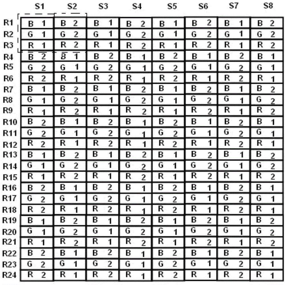
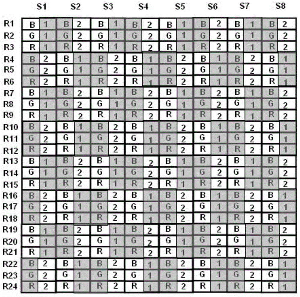
[0042] This embodiment provides a display driving method, the method is used to drive a 3D display device, the 3D display device includes: a pixel array and a grating arranged on the light emitting surface of the pixel array; wherein, the pixel array includes a plurality of first A pixel unit and a plurality of second pixel units, and the first pixel unit and the second pixel unit are alternately arranged in the row direction and the column direction; the first pixel unit and the second pixel unit include N different pixel units arranged in the same column The sub-pixel of the color; the grating includes a plurality of light-shielding regions and a plurality of light-transmitting regions alternately arranged in the row direction and in the column direction, and each light-shielding region is used to shield the first side of the first pixel unit adjacent in the row direction and the second side of the second pixel unit; the first side and the second side are opposite sides. Sin...

Embodiment 2

[0063] This embodiment provides a display driving device, which is used to drive a 3D display device, and the 3D display device includes: a pixel array and a grating arranged on the light-emitting surface of the pixel array; wherein, the pixel array includes a plurality of first A pixel unit and a plurality of second pixel units, and the first pixel unit and the second pixel unit are alternately arranged in the row direction and the column direction; the first pixel unit and the second pixel unit include N different pixel units arranged in the same column The sub-pixel of the color; the grating includes a plurality of light-shielding regions and a plurality of light-transmitting regions alternately arranged in the row direction and in the column direction, and each light-shielding region is used to shield the first side of the first pixel unit adjacent in the row direction and the second side of the second pixel unit; the first side and the second side are opposite sides; the d...


PUM


Abstract

The invention provides a display driving method and a display driving device, belongs to the technical field of display and can solve the problem that the existing 3D display device has relatively low resolution. The display driving method is used for driving the 3D display device and comprises the following steps: S1, calculating color components of each sub-pixel in multiple first pixel units for displaying a first view and multiple second pixel units for displaying a second view; S2, determining a sampling region of each sub-pixel, and determining the brightness of the sub-pixel according to the color components of the sub-pixel in each pixel unit covered by the sampling region corresponding to the sub-pixel, wherein the sampling region is a rhombic sampling region; four vertices of the rhombic sampling region are midpoints of lines of centers of four sub-pixels adjacent and similar to the sub-pixel in columns adjacent to the sub-pixel; similar sub-pixels of one sub-pixel refer to the sub-pixels which belong to the pixel unit of the same view of the sub-pixel and have the same color of the sub-pixel.

Description

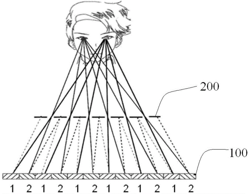
technical field [0001] The invention belongs to the field of display technology, and in particular relates to a display driving method and a display driving device. Background technique [0002] figure 1 Shown in is a schematic diagram of an implementation of naked-eye stereoscopic display. All the pixels 1 on the display panel 100 are used to display images for the left eye, and enter the left eye of the viewer after passing through the grating 200; Eye, left-eye image and right-eye image are synthesized into a stereoscopic image in the human brain. [0003] However, using figure 1 When the naked-eye stereoscopic display is implemented in the display device shown in , some pixels in the display device are used to display the left-eye image, and the other part of the image is used to display the right-eye image, resulting in a decrease in the resolution of the naked-eye stereoscopic display. [0004] Therefore, when using a display device for stereoscopic display, how to...

Claims


Application Information

Patent Timeline
Patent Type & Authority Applications(China)
IPC IPC(8): G09G3/36G09G3/34
CPCG09G3/3611H04N13/31H04N13/317H04N13/324G09G3/003G09G3/2003G09G3/348G09G2300/0404G09G2300/0452G09G2340/0457G09G2360/16G09G3/36G09G2320/0233G09G5/10
Inventor 郭仁炜董学
Owner BOE TECH GRP CO LTD
Learn More