An Improved Power Management Device

A technology of power management device and power conversion module, which is applied in the direction of emergency protection circuit devices and electrical components, and can solve problems such as unstable power output and mismatching of power usage

Inactive Publication Date: 2017-06-16
SHENZHEN JIUZHOU ELECTRIC
View PDF6 Cites 0 Cited by
  • Summary
  • Abstract
  • Description
  • Claims
  • Application Information

AI Technical Summary

Problems solved by technology

[0006] The technical problem to be solved by the present invention is to overcome the problems in the prior art that the power output is unstable under the control of the power circuit and the power used by the power supply does not match.

Method used


Image

  • An Improved Power Management Device
  • An Improved Power Management Device
  • An Improved Power Management Device

Examples


Embodiment 1

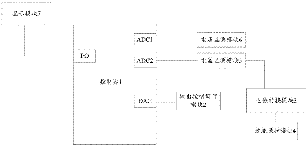
[0036] Embodiment 1 of the present invention provides an improved power management device, characterized in that the power management device includes a controller 1, an output control adjustment module 2, a power conversion module 3 and an overcurrent protection module 4, specifically:

[0037] The controller 1 is connected to the output control adjustment module 2, and the controller 1 is used to send a signal to adjust the output voltage or adjust the current limiting threshold of the overcurrent protection module 4 to the output control adjustment module 2; the output The control adjustment module 2 is connected to the power conversion module 3, and is used to complete the circuit corresponding to the output voltage or the current limit threshold after receiving the signal for adjusting the output voltage or the current limit threshold of the overcurrent protection module 4 Adjustment;

[0038] The power conversion module 3 is based on the power supply, and outputs a stable...

Embodiment 2

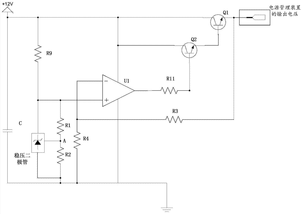
[0046] This embodiment is implemented based on the power management device disclosed in Embodiment 1, and how to implement the power conversion module 3 is described through specific examples. In this example, if figure 2 As shown, the power conversion module 3 includes a voltage stabilizing module, specifically:

[0047] The voltage stabilizing module is composed of an integrated power amplifier U1, and the positive input port of the integrated power amplifier U1 is connected in series with a resistor R1 and a resistor R2 and then grounded;

[0048] A Zener diode is connected in parallel at both ends of the resistor R2, and the forward voltage of the integrated power amplifier U1 is generated through the reference voltage VREF provided by the Zener diode;

[0049] The output port of the power management device is connected in series with the resistor R3 and the resistor R4 and grounded, and the inverting input port of the integrated power amplifier U1 is connected between t...

Embodiment 3

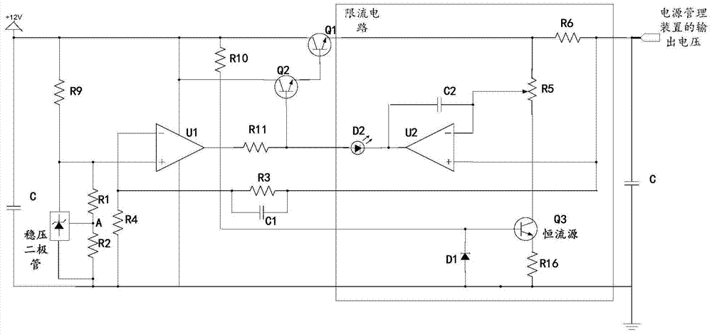
[0055] This embodiment is implemented based on the power management device disclosed in Embodiment 1 and / or Embodiment 2, and how to implement the overcurrent protection module 4 is described through specific examples. In this example, if image 3 The overcurrent protection module 4 shown includes a current limiting circuit, and the output port of the current limiting circuit is connected to the output port of the voltage stabilizing module, specifically:

[0056] The current limiting circuit is composed of an integrated power amplifier U2, the positive input port of the integrated power amplifier U2 is connected to the output port of the power management device;

[0057] The inverting input port of the integrated power amplifier U2 is connected to the output port of the power management device through a resistor R5 and a resistor R6; wherein, the resistor R6 is connected in series on the output line of the power management device, and the power management device The output c...


PUM


Abstract

An improved power source management device comprises a controller (1), an output control adjustment module (2), a power source conversion module (3) and an over-current protection module (4). The controller (1) is connected to the output control adjustment module (2), and is used to transmit, to the output control adjustment module (2), a signal for adjusting an output voltage or adjusting a current limit threshold of the over-current protection module. The output control adjustment module (2) is connected to the power source conversion module (3), and is used to adjust a circuit corresponding to the signal after the signal for adjusting the output voltage or adjusting the current limit threshold of the over-current protection module is received. The power source conversion module (3) outputs, based on a power supply and via a conversion, a stable voltage. The over-current protection module (4) is connected to the power source conversion module (3), and is used to stop a voltage output after output current exceeds a preset value. The power source management device addresses the problem in which a power source system easily malfunctions as a result of an unstable power source output.

Description

[0001] 【Technical field】 [0002] The invention relates to the technical field of power circuits, in particular to an improved power management device. [0003] 【Background technique】 [0004] The power supply circuit of electronic products is an important part of the whole product, with simple or complex topology, different products will match different electrical properties according to the market, such as short circuit protection, over current protection, over temperature protection, automatic adjustment, with timing control Wait, the more functions the power conversion chip has, the higher the integration level will be, and the corresponding cost will also increase. In addition, most electronic products (such as set-top boxes, mobile phones, routers, etc.) are damaged. According to maintenance statistics, power system failures and damages account for the vast majority. Common interface plug-in short circuit, unstable power output, power mismatch and so on are the main caus...

Claims


Application Information

Patent Timeline
Patent Type & Authority Patents(China)
IPC IPC(8): H02H7/10
CPCH02H7/10
Inventor 张嘉
Owner SHENZHEN JIUZHOU ELECTRIC
Why Eureka
Try Eureka