Electric tying machine

A kind of tying machine and electric technology, which is applied in packaging machines, packaging, transportation and packaging, etc., can solve the problems of complex structure, easy failure and high cost, and achieve the effect of simplifying the structure, reducing the failure rate and facilitating the operation.

Inactive Publication Date: 2014-09-10
HENAN UNIV OF SCI & TECH
View PDF12 Cites 3 Cited by
  • Summary
  • Abstract
  • Description
  • Claims
  • Application Information

AI Technical Summary

Problems solved by technology

[0007] The purpose of the present invention is to provide an electric binding machine to solve the problems of complex structure, high cost and easy failure of existing automatic binding machines

Method used


Image

  • Electric tying machine
  • Electric tying machine

Examples


Embodiment Construction

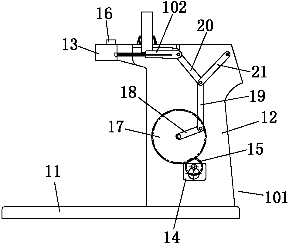
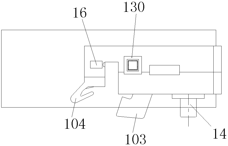
[0018] Examples of electric tying machines, such as Figure 1-2 As shown, the electric binding machine includes a frame 101, a push rod 102 and a push rod driving mechanism.

[0019] The frame 101 comprises a base 11, a stand 12 and a cross arm 13, the cross arm 13 is provided with a nail inlet 130, and the push rod is assembled on the cross arm 13, wherein the structure of the nail inlet 130, the push rod 102 and The relative positional relationship between the nail inlet 130 and the push rod 102 is the prior art, and will not be described in detail here. In addition, the cross arm 13 is also respectively provided with a bag pressing block 103 and a blade 104, wherein the bag pressing block 103 and the The blade 104 is also a prior art, and will not be repeated here.

[0020] The push rod driving mechanism includes a power part and a transmission part, and the power part includes a motor 14. In this embodiment, the motor 14 specifically adopts a geared motor, which can be a ...


PUM


Abstract

The invention relates to packaging bag tying equipment, in particular to an electric tying machine comprising a frame, a push bar, and a push bar drive mechanism; the push bar drive mechanism comprises a power portion and a transmission portion; the power portion comprises a motor; the transmission portion comprises a crank, a middle link, an output link, and an auxiliary link; one end of the middle link is connected with the crank; the other end of the middle link is connected with the corresponding end of the output link and the correspond end of the auxiliary link; the output link is connected with the push bar; the auxiliary link is connected with the frame; the output link and the auxiliary link are in V-shape distribution. By the use of the electric tying machine, the problems that the existing automatic tying machine is complex in structure and high in cost and fails easily are solved.

Description

technical field [0001] The invention relates to a packaging bag binding device, in particular to an electric binding machine. Background technique [0002] With the continuous popularization of various disposable packaging bags, the sealing machine has been widely used today. The nailing machine is one of the nailing machines. The nailing machine is very popular in the retail industry because it is not easy to open and environmentally friendly. Therefore, the nailing machine has become a lot of The most widely used type of binding machine. [0003] At present, the vast majority of visible binding machines on the market are manual. The main components of the manual binding machine are brackets, push rods and crank rods. The bracket is provided with a nail inlet, which is used for Install nails to tie the bag; the push rod is used to push the nail and tie the bag, and the crank rod is used as the operating handle of the tie machine, which is connected with the push rod drive...

Claims


Application Information

Patent Timeline
Patent Type & Authority Applications(China)
IPC IPC(8): B65B65/02
Inventor 张伏王俊邱兆美王唯刘红梅岳斌斌张亚坤
Owner HENAN UNIV OF SCI & TECH
Why Eureka
Try Eureka