Magnetic transmission device

A technology of magnetic transmission and magnetic barrel, which is applied in the direction of electromechanical transmission devices, electromechanical devices, electric components, etc., can solve the problems of large pressure difference on the output shaft of the motor and the inability to realize effective dynamic sealing, etc., and achieves convenient interface connection, simple and reliable structure, achieve the effect of isolation

Inactive Publication Date: 2015-06-03
BEIJING RES INST OF PRECISE MECHATRONICS CONTROLS
View PDF7 Cites 2 Cited by
  • Summary
  • Abstract
  • Description
  • Claims
  • Application Information

AI Technical Summary

Problems solved by technology

[0003] Aiming at the defects in the prior art, the present invention provides a magnetic transmission device, thereby solving the shortcomings and deficiencies in the prior art of the large pressure difference at the output shaft of the motor and the inability to realize effective dynamic sealing

Method used


Image

  • Magnetic transmission device
  • Magnetic transmission device
  • Magnetic transmission device

Examples


specific Embodiment approach 1

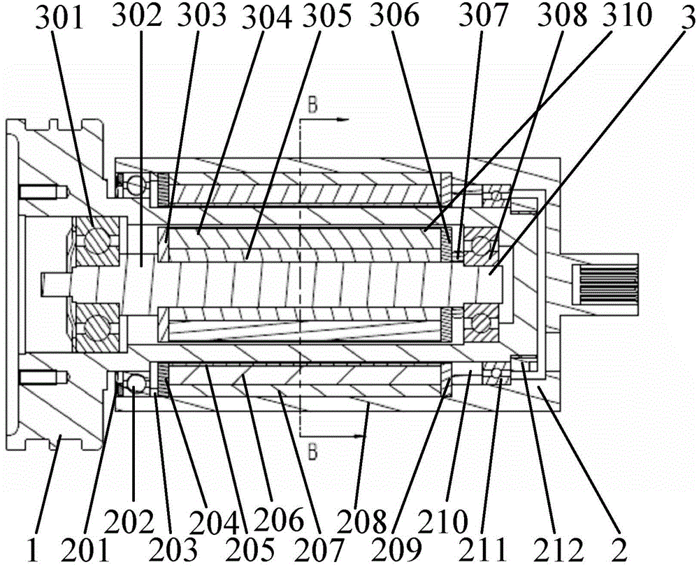
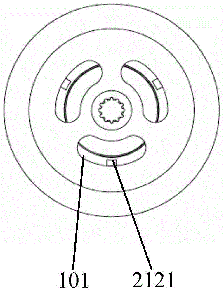
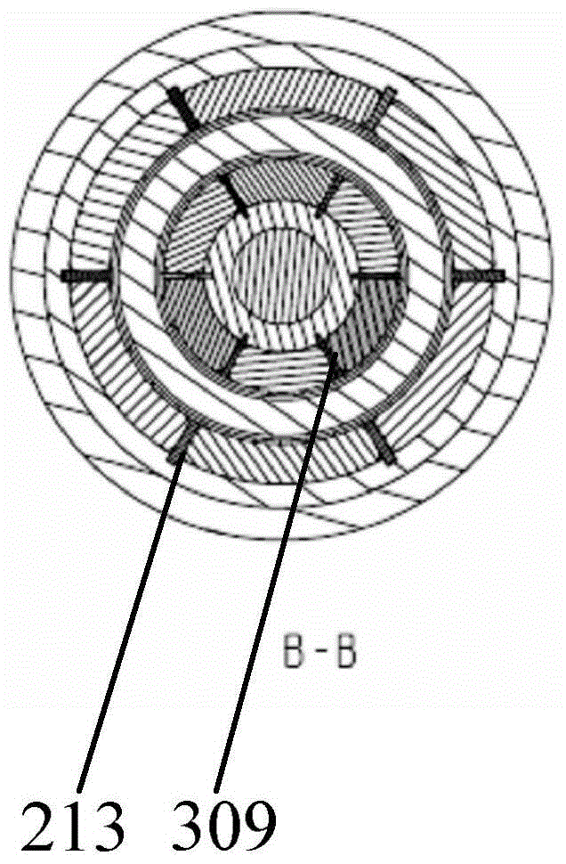
[0020] Specific Embodiment 1: Combining Figure 1~3 This embodiment will be described. A magnetic transmission device in this embodiment includes an isolation barrel 1, an outer magnetic barrel 2, and a magnetic shaft 3. The outer magnetic barrel 2 includes a wave spring 201, a bearing 202, a bearing retaining ring 203, and a magnetic steel retaining ring 204, which is one side Outer seal retaining ring, magnetic steel tight sleeve 205, magnetic steel barrel 206, magnetic steel seat 207, outer sleeve 208, magnetic steel retaining ring 209, bearing retaining ring 210 is the outer sealing retaining ring on the other side, bearing 211, fastening Cover 212, magnetic steel retainer 213. Wherein, the magnetic steel bucket 206 is composed of multiple pieces of permanent magnetic steel, such as 6, 8 or 10 pieces of permanent magnetic steel, and the magnetic steel bucket 206 is fixedly connected with the inner wall of the outer sleeve 208 . The magnetic shaft 3 includes a bearing 301...

specific Embodiment approach 2

[0022] Specific Embodiment 2: Combining figure 1 This embodiment will be described. The difference between this embodiment and specific embodiment 1 is that the drive shaft of the motor can be connected with the inner shaft 302 of the magnetic conduction shaft 3, and the end shaft of the outer sleeve 208 can be used as the output shaft to work, so that the motor can be directly connected with the The external magnetic barrel is connected to realize power transmission, eliminating the need for intermediate coupling links.

specific Embodiment approach 3

[0023] Embodiment 3: Combining figure 1 This embodiment will be described. This embodiment differs from Embodiment 1 in that the number of magnetic steel barrels 206 and magnetic permeable barrels 304 is not limited to six. Other compositions and connection methods are the same as in Embodiment 1.


PUM


Abstract

The invention discloses a magnetic transmission device which comprises a magnetic conductive shaft, an outer magnetic barrel and an isolating barrel, wherein the outer magnetic barrel is movably connected outside the isolating barrel and is positioned on one side of the isolating barrel; the magnetic conductive shaft is movably connected into the isolating barrel and is positioned on the other side of the isolating barrel; therefore when the outer magnetic barrel rotates, the magnetic conductive shaft is driven to rotate. The defects and the shortcomings of large pressure difference and non implementation of effective dynamic sealing at an output shaft of a motor in the prior art are overcome; a simple brush motor is possibly controlled and driven to be used as an under-well prime motor. The magnetic transmission device is simple and reliable in structure and convenient and quick for interface connection, and a good solution is provided for power selection of an under-well tool.

Description

technical field [0001] The invention relates to the field of oil exploitation, in particular to a magnetic transmission device. Background technique [0002] At present, the working environment of downhole tools in the field of petroleum exploration and development is relatively harsh, and most of them belong to high-temperature and high-pressure liquid environments. The motor is immersed in lubricating oil to work, and the external environment pressure is introduced into the lubricating oil to balance the internal and external pressure. In this way, the large pressure differential seal at the rotating shaft is converted into a zero pressure differential seal, which realizes the protection of the motor from the external mud. environmental isolation. But at present, the choice of motor for this solution must be a brushless motor, and the brushless motor requires a special drive control circuit, which complicates the power supply and control on the well. In addition, the zero...

Claims


Application Information

Patent Timeline
IPC IPC(8): H02K51/00
Inventor 秦二卫张达张朝阳胡林王恒
Owner BEIJING RES INST OF PRECISE MECHATRONICS CONTROLS
Why Eureka
Try Eureka