Permanent magnet coupler

A permanent magnet coupler and permanent magnet technology, applied in the direction of electrical components, electromechanical devices, electromechanical transmission devices, etc., can solve the problems of lack of vibration isolation, energy saving, and waste of electric energy

Inactive Publication Date: 2015-06-03
盐城华力达科技有限公司
View PDF3 Cites 2 Cited by
  • Summary
  • Abstract
  • Description
  • Claims
  • Application Information

AI Technical Summary

Problems solved by technology

[0003] The existing motor system has a serious waste of electric energy, and the traditional mechanical coupling inevitably transmits vibration from one end to the other through the coupling, which obviously does not have the performance of vibration isolation and energy saving

Method used


Image

  • Permanent magnet coupler
  • Permanent magnet coupler

Examples


Embodiment Construction

[0016] In order to make the technical means, creative features, goals and effects achieved by the present invention easy to understand, the present invention will be further described below in conjunction with specific embodiments.

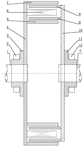
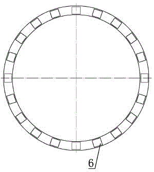
[0017] As shown in the figure, a permanent magnetic coupler includes a split shaft A1 and a shaft B9. The shaft A1 and the shaft B9 are coaxial. The inner cylinder 5, the carrying magnet 6 and the outer cylinder 7 are arranged in sequence. A circle of permanent magnets is installed on the carrying magnet 6. The magnetic pole direction of the permanent magnet is perpendicular to the axis of the permanent magnet turntable, and the magnetic poles of adjacent magnets are installed at different poles; The turntable 10, the conductor turntable 10 is provided with at least one conductor cylinder 8, and the conductor cylinder 8 is arranged in the gap between the inner and outer cylinders and the magnet-carrying body.

[0018] The permanent magnet turntabl...


PUM


Abstract

The invention discloses a permanent magnet coupler. The permanent magnet coupler comprises a shaft A and a shaft B which are separated, wherein the shaft A and the shaft B are coaxial; a permanent magnet rotary table is arranged on the shaft A; an inner barrel, a carrying magnet and an outer barrel are arranged on the permanent magnet rotary table in sequence from inside to outside; a circle of permanent magnets are mounted on the carrying magnet; the magnetic pole directions of the permanent magnets are vertical to the axis of the permanent magnet rotary table, and the magnetic poles of adjacent magnets are mounted in a heterospolar mode; a conductor rotary table is arranged on the shaft B, one or more conductor barrels are arranged on the conductor rotary table, and the conductor barrels are arranged in the gaps among the inner barrel, the outer barrel and the carrying magnet. According to the invention, N and S poles of the magnets are arranged in an adjacent mode, a magnetic line passes through the corresponding conductor barrel, and when the magnetic line and the corresponding conductor barrel move relative to each other, the magnetic line is cut by the corresponding conductor barrel, eddy current is generated in the conductor barrel, and then an opposite sensing magnetic field is generated by the eddy current, so that the relative movement between the magnetic line and the corresponding conductor barrel is prevented, the torque transmission between the magnetic line and the corresponding conductor barrel is realized, and the purposes of vibration isolation, speed reduction and energy reduction are achieved.

Description

technical field [0001] The invention belongs to the field of mechanical drive, in particular to a permanent magnet coupler adopting the principle of permanent magnet eddy current induction. Background technique [0002] Permanent magnet coupler, also known as magnetic coupler, is a device that realizes the torque transmission from the motor to the load through the air gap between the conductor and the permanent magnet. It can realize the transmission mode without mechanical connection between the motor and the load. Its working principle When the two move relative to each other, the conductor assembly cuts the magnetic force line, generates eddy current in the conductor, and the eddy current then generates an anti-magnetic field, which interacts with the magnetic field generated by the permanent magnet, so as to realize the torque transmission between the two. [0003] The existing motor system has a serious waste of electric energy, and the traditional mechanical coupling i...

Claims


Application Information

Patent Timeline
Patent Type & Authority Applications(China)
IPC IPC(8): H02K51/00
Inventor 茆华忠吴春光
Owner 盐城华力达科技有限公司
Why Eureka
Try Eureka