Energy return system

A technology for energy return and orthosis, applied in clothing, footwear, applications, etc., to solve problems such as increased pressure on the dermis

Active Publication Date: 2015-06-03
巴里 A 巴特勒
View PDF7 Cites 11 Cited by
  • Summary
  • Abstract
  • Description
  • Claims
  • Application Information

AI Technical Summary

Problems solved by technology

This rupture may cause increased pressure on the dermis
Although there are devices and methods aimed at preventing the formation of planar ul

Method used


Image

  • Energy return system
  • Energy return system
  • Energy return system

Examples


Embodiment Construction

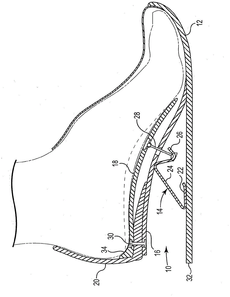
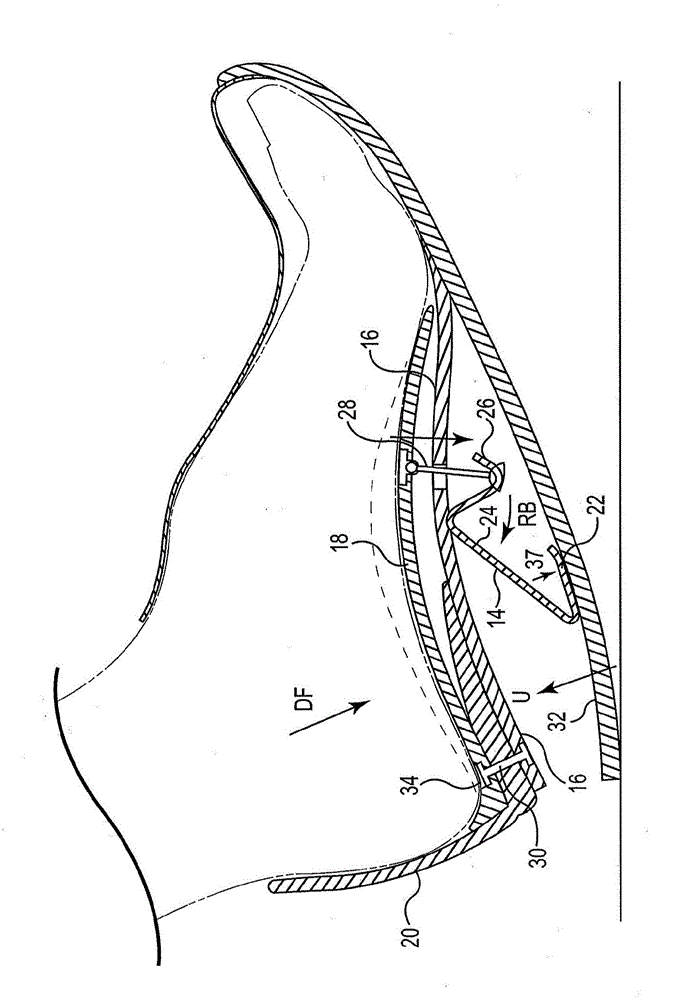
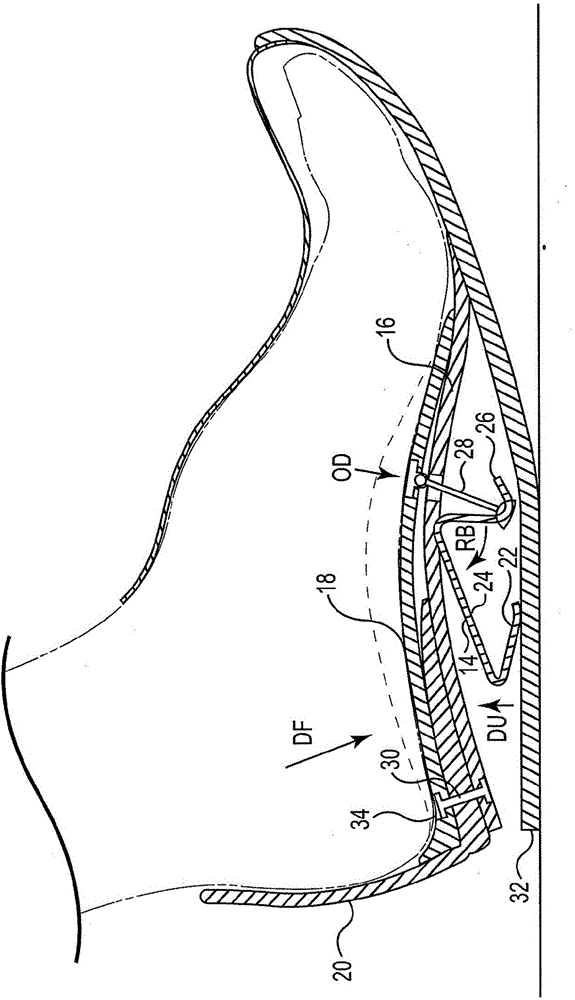
[0113] now refer to Figure 1-6 , describing a first embodiment of an orthotic energy return system according to the present invention. figure 1A foot is shown at rest wearing an energy return system 10 according to the present invention (two-dashed line). Energy return system 10 is shown in an unloaded or unloaded position with substrate layer 12 at rest on a surface (eg, the ground). Energy return system 10 broadly includes substrate layer 12 , rod 14 , platen 16 and aligner 18 . Base 12 may be of any length so long as the length extends generally from the sole of the foot to the toe area. Substrate 12 may comprise any material used in shoe soles, including, but not limited to, rubber, plastic, polymers, polyurethane, and the like. The rod 14 includes a sliding portion 22 , an inclined central portion 24 and an inclined connecting portion 26 . The rod 14 is made of a resilient material to allow dynamic deformation of the rod during the gait cycle. Suitable materials tha...


PUM


Abstract

A tri-layer energy return system is provided. The tri-layer energy return system includes a base; an orthotic; a platen directly or indirectly operably coupled to the base, the orthotic or both. A lever including a slide portion is movably received by said base. A tensioning member is coupled to said orthotic at an attachment point thereof.

Description

technical field [0001] The present invention relates generally to orthotics, and more particularly, to dual-layer and triple-layer orthotics configured to absorb energy and then return energy to the individual wearer's foot. Background technique [0002] Walking and running can be defined as methods of locomotion involving the alternate use of two legs for both support and propulsion with at least one foot in constant contact with the ground. Although the terms gait and walking are often used interchangeably, the word gait refers to the manner or style of walking rather than the actual process of walking. A gait cycle is the time interval between identical repeated walking events. [0003] The defined period may begin at any time, but typically begins when one foot touches the ground and ends when that foot touches the ground again. If the cycle started when the right foot hits the ground, the cycle ends when the right foot hits the ground again. Thus, each cycle begins w...

Claims


Application Information

Patent Timeline
IPC IPC(8): A43B13/14A43B13/28
CPCA43B7/14A43B13/145A43B13/183A43B13/184
Inventor 巴里·A·巴特勒
Owner 巴里 A 巴特勒
Why Eureka
Try Eureka