
Folding releasing joint and children stroller

A technology of joints and substrates, which is applied in the field of folding release joints and children's strollers, can solve the problems of stuck, high production cost, long installation time of rods, etc., and achieve the effect of saving costs and reducing rods

Inactive Publication Date: 2015-06-10
苏州逗乐儿童用品有限公司
View PDF4 Cites 12 Cited by
  • Summary
  • Abstract
  • Description
  • Claims
  • Application Information

AI Technical Summary

Problems solved by technology

[0002] In the prior art, the children's stroller includes a stroller frame, a front wheel assembly, and a rear wheel assembly. The stroller frame includes a front wheel bracket, a rear wheel bracket, and a push handle. The rear wheel assembly is arranged at the rear and lower part of the wheel frame. Usually, a connecting rod must be arranged between the front wheel bracket and the rear wheel bracket. The front end of the connecting rod is rotatably connected with the front wheel bracket. When the cart frame is unfolded and folded, the connecting rod drives the front wheel bracket or the rear wheel bracket to enter the folded state. However, due to the large number of rods in this type of frame, the installation time of the rods is longer and the production cost is relatively high. In addition, when folding or opening, sometimes it will be stuck, and the force required for folding or unfolding is relatively large

Method used


Image

  • Folding releasing joint and children stroller
  • Folding releasing joint and children stroller
  • Folding releasing joint and children stroller

Examples


Embodiment Construction

[0022] The specific implementation manners of the present invention will be further described in detail below in conjunction with the accompanying drawings and embodiments. The following examples are used to illustrate the present invention, but are not intended to limit the scope of the present invention.

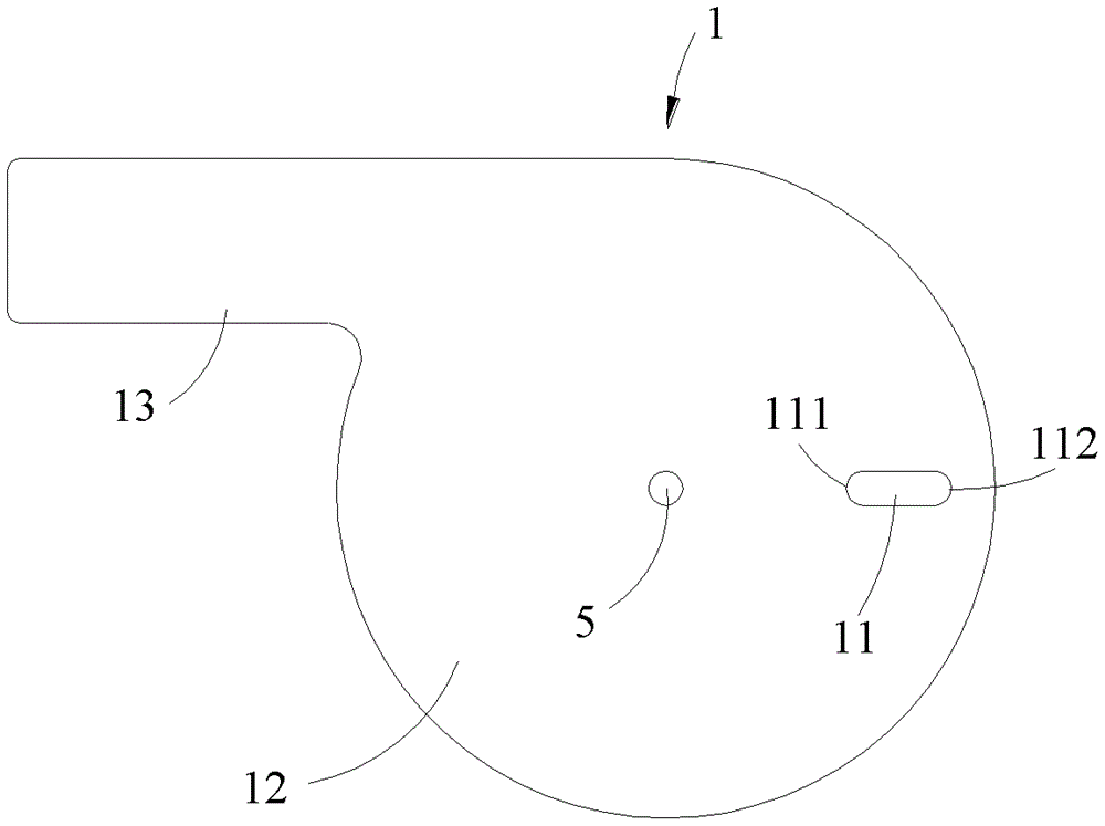
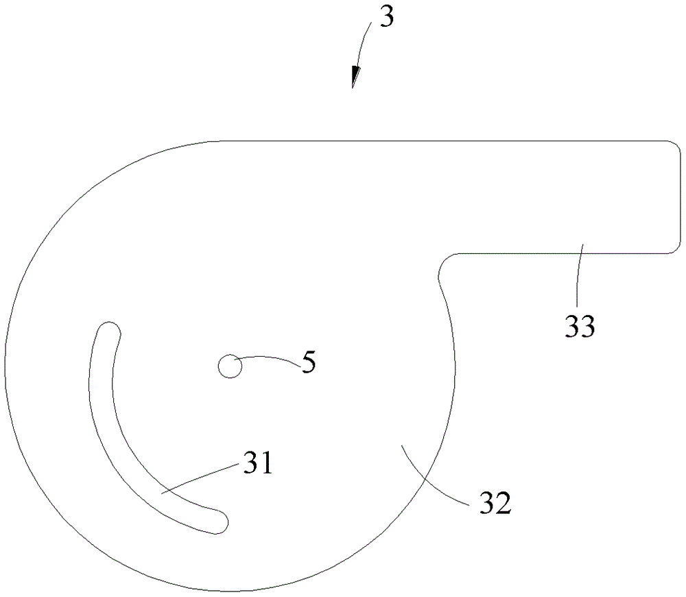
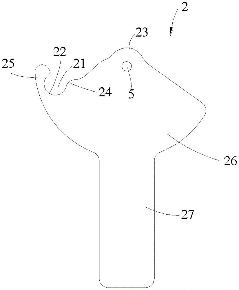
[0023] see Figure 1 to Figure 5 A folding release joint described in a preferred embodiment of the present invention includes a rotating shaft (not shown), a first base plate 1, an intermediate plate 2 and a second base plate 3 connected in turn by the rotating shaft, and connecting the first base plate 1 and the second base plate The connecting rod 4 of the second base plate 3 , the first base plate 1 , the middle plate 2 and the second base plate 3 are respectively provided with shaft holes 5 through which the shaft passes. The first substrate 1 and the second substrate 3 are respectively q-shaped, wherein the first substrate 1 has a circular first plate body 12 and a ...


PUM


Abstract

The invention relates to a folding releasing joint and a children stroller. The folding releasing joint comprises a rotating shaft, a first baseplate, a middle plate, a second baseplate, and a connecting bar, wherein rotating shaft holes allowing a rotating shaft to penetrate are formed in the first baseplate, the middle plate and the second baseplate; a long hole extending in the radial direction of the rotating shaft hole is formed in the first baseplate; an open slot is formed in the middle plate; an arc-shaped groove is formed in the second baseplate; the semidiameters of the arc-shaped groove are diminished in sequence in the folding direction of the folding releasing joint by adopting the rotating shaft hole as a center; the first baseplate and the second baseplate are arranged on the two sides of the middle plate respectively; the two sides of the connecting bar protrude and extend respectively to form a first shaft part inserted into the long hole in the first baseplate and a second shaft part inserted into the arc-shaped groove in the second baseplate; the first shaft part and the second shaft part can move in the long hole and the arc-shaped groove respectively; a clamping block is arranged at the bottom far away from the first shaft part and near the second shaft part of the connecting bar; the outer edge surface of the clamping block is an arc-shaped surface; the clamping block is clamped in the open slot.

Description

technical field [0001] The invention relates to a folding release joint and a stroller for children. Background technique [0002] In the prior art, a children's stroller includes a stroller frame, a front wheel assembly, and a rear wheel assembly. The stroller frame includes a front wheel bracket, a rear wheel bracket, and a push handle. The rear wheel assembly is arranged on the rear and lower part of the wheel frame. Usually, a connecting rod must be arranged between the front wheel bracket and the rear wheel bracket. When the cart frame is unfolded and folded, the connecting rod drives the front wheel bracket or the rear wheel bracket to enter the folded state. However, due to the large number of rods in this kind of frame, the installation time of the rods is longer and the production cost is relatively high. In addition, when folding or opening, sometimes it will be stuck, and the force required for folding or unfolding is relatively large. [0003] In view of the ab...

Claims


Application Information

Patent Timeline
IPC IPC(8): B62B7/06
Inventor 艾少鸿
Owner 苏州逗乐儿童用品有限公司
Learn More