
Sheet conveying device

A conveying device and sheet material technology, applied in the direction of transportation and packaging, object separation, pile separation, etc., can solve problems such as entry, and achieve the effect of inhibiting the entry of foreign objects and dust, etc.

Active Publication Date: 2015-06-10
BROTHER KOGYO KK
View PDF6 Cites 0 Cited by
  • Summary
  • Abstract
  • Description
  • Claims
  • Application Information

AI Technical Summary

Problems solved by technology

[0008] However, since the paper output tray described in Patent Document 2 is provided with a through portion for the user to operate the operation portion of the locking mechanism, there is a small chance that foreign matter, dust, etc. enter the paper feeding cassette from the through portion. possibility

Method used


Image

  • Sheet conveying device
  • Sheet conveying device
  • Sheet conveying device

Examples


Embodiment Construction

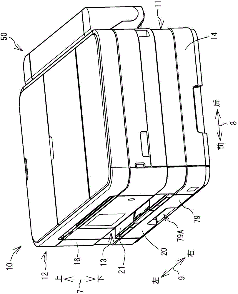
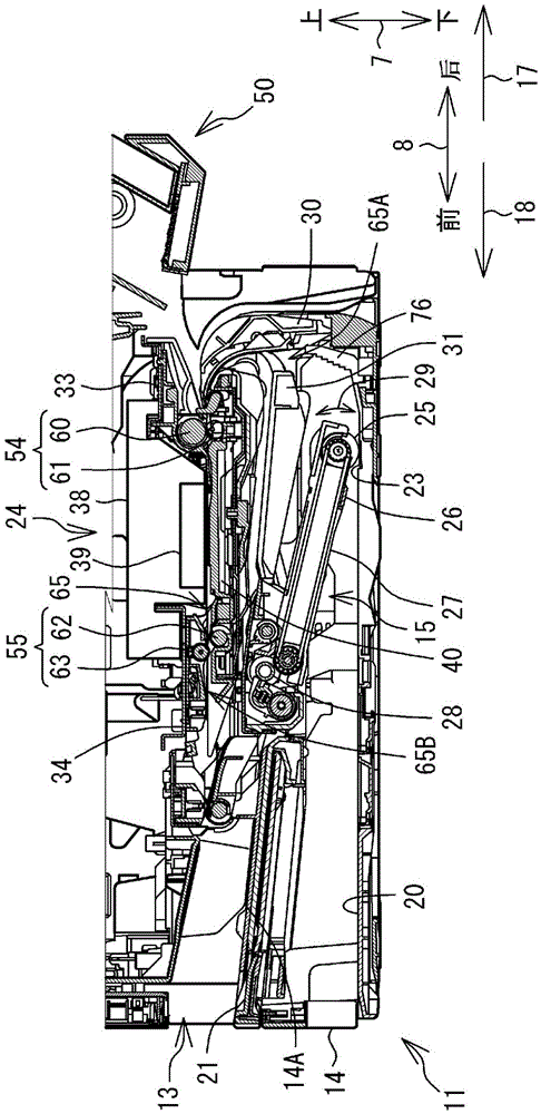
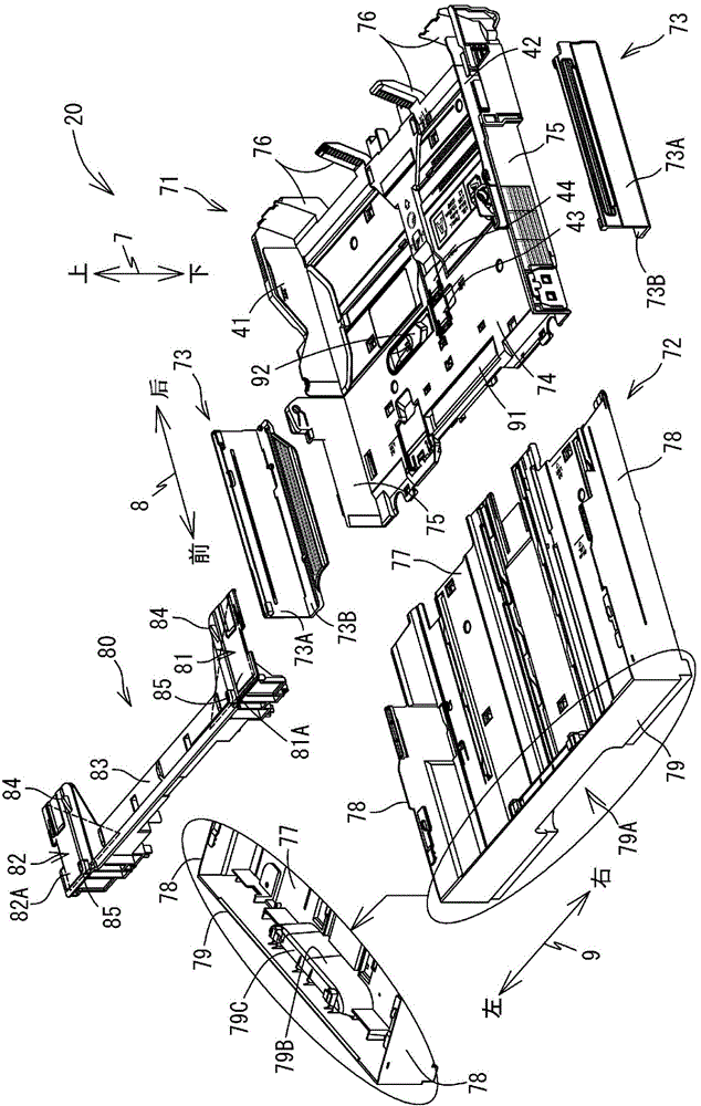
[0034] Embodiments of the present invention will be described below. In addition, the embodiment described below is merely an example of the present invention, and it is needless to say that the embodiment of the present invention can be appropriately changed within a range that does not change the gist of the present invention. In addition, in the following description, it is assumed that the multifunction peripheral 10 is set in a usable state ( figure 1 state) as a reference to define the up-down direction 7, define the front-rear direction 8 with the side provided with the opening 13 as the front side (front), and define the left-right direction 9 when viewing the MFP 10 from the near side (front). In addition, the front-back direction 8 is an example of the first direction, and the left-right direction 9 is an example of the second direction.

[0035]

[0036] Such as figure 1 As shown, the multifunction peripheral 10 is formed in a substantially rectangular parallele...


PUM


Abstract

The invention provides a sheet conveying device, comprising a feeding tray supporting sheets, a conveying portion conveying sheets supported on the feeding tray, and a discharge tray which is supported on the feeding tray in a manner of rotating between a falling position and a standing position and supports the sheets, the sheets being conveyed by the conveying portion. The feeding tray is provided with a first tray, a second tray which moves relative to the first tray between a first position and a second position, and a locking mechanism limiting movement of the second tray. The locking mechanism is provided with a clamping component and an operating component. The clamping component moves between a clamping position and a clamping removing position, the first tray and the second tray being clamped on the clamping position, and clamping of one of the first tray and the second tray being removed on the clamping removing position. On the position overlapped with the rotary axis of the discharge tray, the operating component makes the clamping component moves between a locking position and a locking remove position, the locking position being on the clamping position, and the locking remove position being on the clamping removing position.

Description

[0001] This application claims the priority of Japanese Patent Application No. 2013-253544 for which it applied on December 6, 2013, and uses all the content disclosed by the said patent application here. technical field [0002] The present invention relates to a sheet transport device including a feed tray capable of supporting sheets of various sizes. Background technique [0003] Conventionally, image recording devices such as copiers and printers are equipped with sheet conveying devices. The sheet transport device includes a feed tray that supports sheets in a stacked state, and a transport unit that transports the sheets supported by the feed tray. Furthermore, in response to demands for miniaturization of image recording devices in recent years, the supply tray has also been miniaturized. As a result, it is difficult to accommodate large-sized sheets in the feed tray mounted on the image recording apparatus. [0004] In order to solve the above-mentioned problems, ...

Claims


Application Information

Patent Timeline
IPC IPC(8): B65H1/26
Inventor 杉山亘鹫野善行
Owner BROTHER KOGYO KK
Learn More